Antenna Near Field & Far Field Distance Calculator
Antenna Near Field & Far Field Distance Calculator
Calculate the approximate reactive near-field, radiating near-field, and far-field distances of an antenna from its operating frequency and maximum antenna dimension.
How Is Antenna Near-Field and Far-Field Distance Calculated?
The wavelength is calculated from the operating frequency:
where c is the speed of light (299,792,458 m/s) and f is frequency in hertz.
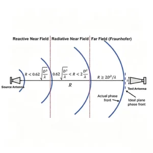
Reactive Near Field
For electrically large antennas, a commonly used approximate outer boundary of the reactive near field is:
Very close to the antenna, reactive electric and magnetic field components can be significant and the local field can be strongly affected by nearby objects.
Radiating Near Field
For electrically large antennas, the radiating near field (Fresnel region) lies approximately between the reactive near-field boundary and the far-field boundary:
Radiation dominates in this region, but the angular field distribution can still vary with distance.
Far Field
A widely used Fraunhofer/Rayleigh estimate for electrically large antennas is:
Beyond this distance, the angular radiation pattern is treated as essentially independent of distance for the chosen approximation.
What Does D Mean in the Formula?
D is the maximum linear dimension of the antenna or relevant radiating aperture. For a directional panel or array, use the dimension that best represents the largest extent of the radiating structure for the measurement criterion being applied.
The distinction matters because the commonly used Fraunhofer estimate grows with the square of D:
Doubling the antenna dimension therefore increases the calculated far-field distance by approximately four times when frequency is unchanged.
Small Antennas vs. Electrically Large Antennas
The familiar three-region model is most useful when the antenna is electrically large enough for a distinct radiating near-field region to exist. For electrically small antennas, a simpler two-region model is often used: a reactive near field close to the antenna followed by the far field. The exact transition depends on the antenna and the measurement criterion being applied.
For that reason, this calculator does not treat 2D²/λ as a universal answer for very small antennas. When D is less than λ/2, the calculator switches to a small-antenna reference and clearly labels the wavelength-based far-field planning distance as a measurement reference, not a universal field boundary.
Why Far-Field Distance Is Not Just “3–5 Wavelengths”
A few wavelengths can be a useful intuition for some small antennas, but it is not a universal far-field criterion. For an electrically large antenna, the antenna dimension D can dominate the required distance through the 2D²/λ relationship.
For example, a 0.5 m antenna operating at 10 GHz has a wavelength of about 0.03 m, giving an estimated far-field distance of about 16.7 m.
What If the Far-Field Distance Is Too Long?
Large antennas can require very long measurement distances. When a conventional far-field range is impractical, engineers may use near-field scanning and Near-Field to Far-Field (NF-to-FF) transformation, or other specialized measurement methods such as a compact antenna test range.
A near-field measurement is therefore not simply “invalid.” The key is whether the measurement method properly samples the field and converts or interprets the data for the required antenna parameter.
Example: 0.5 m Antenna at 10 GHz
| Parameter | Value |
|---|---|
| Maximum dimension D | 0.5 m |
| Frequency | 10 GHz |
| Wavelength | ≈ 0.03 m |
| Far-field estimate | ≈ 16.7 m |
Need Help With Antenna Testing?
Airplux provides customized antenna solutions for RFID, Wi-Fi, IoT, DAS, base station and other RF applications.
Talk to AirpluxCalculation note: field-region boundaries are approximate. The far-field criterion is commonly expressed using 2D²/λ, but antenna geometry, required accuracy and the selected measurement method can affect the appropriate test distance.
You may also like
Learn how antenna near field and far field regions work, how to calculate far-field distance, and why antenna size matters.

Learn what antenna gain means, how gain relates to directivity and efficiency, how dBi and dBd differ, and how to Choose the Right Gain.

Learn what return loss means, how it is calculated, and how it relates to S11, VSWR, impedance matching, and antenna performance.
Master VSWR vs Return Loss — how they indicate mismatch, reflected power, and why both matter in RF antenna systems.