
What Is Return Loss?
What Is Return Loss?
Table of Contents
- Introduction
- What Is Return Loss?
- Why Does RF Signal Reflection Occur?
- How Is Return Loss Calculated?
- Why Can Return Loss Be Infinite?
- What Is a Good Return Loss?
- Return Loss and Frequency
- Return Loss vs. S11
- Return Loss and VSWR
- How Is Return Loss Measured?
- Why Does Return Loss Matter in RF Engineering?
- Common Return Loss Mistakes
- The Bottom Line
Introduction
Return Loss (RL) is an important RF parameter that tells us how much signal power is reflected back toward the source because of impedance mismatch.
When an RF signal travels through a transmission line, we want as much of its energy as possible to reach the load. If the transmission line and load are not properly matched, part of the signal is reflected instead of being delivered to the load.
Return loss is widely used to evaluate impedance matching in antennas, RF cables, filters, connectors, amplifiers, and other RF components. But what exactly does return loss measure? Why does a higher value indicate better matching? And how is it related to VSWR?
Let’s start with the basic idea.
What Is Return Loss?
Imagine shouting across a valley. When your voice reaches a mountain wall, part of the sound is reflected back, creating an echo.
RF signals can behave in a similar way. When a signal traveling along a transmission line reaches a point where the impedance changes, part of its energy can be reflected back toward the source. The larger the reflected portion, the worse the impedance match.
Return loss tells us how much of the incident signal is reflected, expressed in decibels (dB).
This is why it is closely associated with impedance matching. A high RL means very little power comes back, indicating a good match. A low RL means more power is reflected.
Why Does RF Signal Reflection Occur?
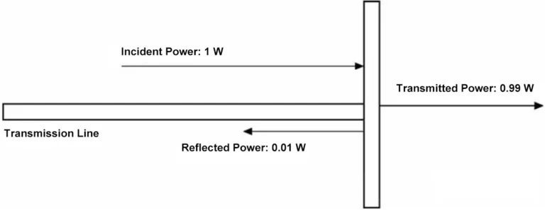
The key concept here is impedance.
Most RF systems use a transmission line with a characteristic impedance of 50 Ω. Ideally, the source, transmission line, connectors, and load should all present compatible impedances to each other.
If a 50 Ω transmission line connects to a load with a very different impedance, the electrical conditions change abruptly at the connection point. That impedance discontinuity causes part of the traveling wave to reflect.

A simple way to picture this is to imagine water flowing through a pipe. If the pipe suddenly changes size, the flow is disturbed at the transition. RF reflection is more precisely governed by electromagnetic boundary conditions, but the analogy helps illustrate why an abrupt impedance change can cause part of the energy to travel back toward the source.
How Is Return Loss Calculated?
-768x188.webp)
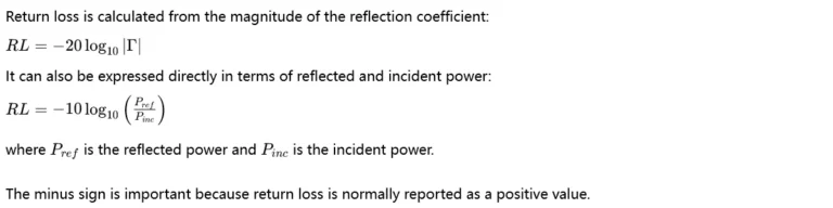
This leads to one of the most common sources of confusion:
A higher return loss means less reflected power and better impedance matching.
For example:
Return Loss | Reflected Power |
0 dB | 100% |
10 dB | 10% |
20 dB | 1% |
30 dB | 0.1% |
So when return loss improves from 10 dB to 20 dB, the reflected power drops from 10% to just 1%.
This is also why the dB scale is so useful in RF engineering: a relatively small numerical change can represent a large change in actual power.
Why Can Return Loss Be Infinite?
With a perfect impedance match, Γ equals zero. The mathematical result for return loss approaches infinity.
In practice, no physical RF system achieves truly infinite return loss. Instruments and components always have finite measurement accuracy and imperfections.
At the other extreme, an ideal open or short circuit has ∣Γ∣=1, giving: RL=0 dB
That represents complete reflection.
What Is a Good Return Loss?

There is no single return loss value that is “good” for every RF application. The required value depends on the component, frequency range, system architecture, and performance target.
For a basic engineering reference, a return loss of around 10 dB corresponds to 10% reflected power, while 20 dB corresponds to only 1%. Many RF designs therefore use 10 dB as a practical reference point, but the actual specification should always come from the requirements of the particular application.
For antennas, for example, a common specification is: Return Loss ≥ 10 dB over the required operating band. This is equivalent to saying that the antenna has a reflection coefficient magnitude no greater than about 0.316, with approximately 10% of the incident power reflected.
Higher return loss indicates a better match, but achieving a much higher value is not automatically necessary. Engineers normally balance impedance matching with other requirements such as antenna efficiency, gain, bandwidth, size, and cost.
Return Loss and Frequency
RL is not normally a single fixed number. It changes with frequency. This becomes particularly obvious when measuring an antenna.
An antenna’s input impedance varies with frequency. Around frequencies where the antenna is well matched to the transmission line, its RL improves and the reflection becomes smaller. Away from those frequencies, the mismatch usually increases. This produces the familiar RL curve seen in antenna measurements.
For example, an antenna may have a RL of 18 dB at 915 MHz but only 6 dB at 800 MHz. Looking at the value at 915 MHz alone would not tell us whether the antenna covers the entire frequency range we need.
That is why engineers normally examine the entire RL curve rather than a single frequency point.
A commonly used antenna bandwidth definition is the -10 dB impedance bandwidth, meaning the frequency range over which the measured reflection coefficient corresponds to a RL of at least 10 dB.
It is worth noting that some RF instruments display S11 in dB, which is normally a negative number. For example, an S11 value of -20 dB corresponds to a RL of 20 dB. So S11 = -20 dB → RL = 20 dB. The two describe the same reflection level using different sign conventions.L
Return Loss vs. S11
RL and S11 are closely related, but they are not exactly the same type of parameter.L

For example, an antenna measurement showing S11 = -15 dB corresponds to a 15 dB RL.
This distinction becomes useful when reading VNA plots and antenna datasheets, because manufacturers may use either term depending on how the measurement is presented.RL
Return Loss and VSWR
Voltage Standing Wave Ratio (VSWR) and RL describe the same underlying impedance-matching condition from different perspectives.
- RL focuses on how much signal is reflected.
- VSWR focuses on the standing-wave pattern created by the interaction of the incident and reflected waves.
They are related through the reflection coefficient: VSWR=1+∣Γ∣/ 1−∣Γ∣
Since RL also depends on ∣Γ∣, the two parameters can be converted directly.
For example:
Return Loss | Approx. VSWR | Reflected Power |
6 dB | 3.0:1 | 25% |
10 dB | 1.92:1 | 10% |
15 dB | 1.43:1 | 3.2% |
20 dB | 1.22:1 | 1% |
30 dB | 1.07:1 | 0.1% |
Neither parameter is inherently “better” than the other. They simply provide different ways to understand impedance matching.
This is why RL and VSWR often appear together in antenna specifications.
How Is Return Loss Measured?
A Vector Network Analyzer (VNA) is commonly used to measure return loss.
1. For a one-port measurement
The VNA sends a signal toward the device under test and measures the reflected signal at the same port. The result is commonly represented by S11.
2. For a two-port measurement
Such as a filter or amplifier, engineers may also examine S22, which describes reflection at port 2. Before taking the measurement, the VNA normally requires a suitable calibration. A common one-port calibration method is OSL (Open, Short, Load) calibration. It helps remove systematic errors introduced by the measurement setup.
The physical test setup also matters. A loose connector, damaged connector, poor cable, or incorrect calibration can introduce additional reflections and make a good device appear to have poor return loss.
3. For multi-port measurements
Unused ports should generally be terminated with appropriate 50 Ω loads according to the measurement configuration. Leaving ports open can introduce additional reflections and change the measured result.
This is particularly important when testing antennas. The antenna’s surroundings can also affect its impedance. Nearby metal objects, cables, mounting structures, and even the final installation enclosure can change the measured return loss.
Why Does Return Loss Matter in RF Engineering?
Return loss is important because impedance mismatch affects how efficiently RF power moves through a system.
Consider a transmitter connected to an antenna. If the antenna presents a poor impedance match, more power is reflected back toward the transmitter instead of being accepted by the antenna.
In a high-power RF system, excessive reflected power can become a serious operating concern. Transmitters and power amplifiers may therefore include protection mechanisms that monitor reflected power or use components such as isolators or circulators in appropriate architectures.
For antennas, return loss also helps engineers determine whether the antenna is properly matched across its intended operating band. But return loss should never be evaluated in isolation.
Antenna performance also depends on parameters such as gain, efficiency, radiation pattern, polarization, bandwidth, and installation environment. An antenna with excellent return loss is not automatically the best antenna for every application.
Common Return Loss Mistakes
One of the easiest mistakes to make is thinking that a smaller return loss is better because the word “loss” sounds negative.
For return loss, the opposite is true: Higher return loss = less reflected power = better impedance matching.
Another common mistake is looking at only one frequency point. An antenna may show excellent return loss at its center frequency while performing poorly near the edges of the required band. For a real RF application, the entire operating range matters.
It is also important not to confuse return loss with antenna efficiency. A well-matched antenna can still have relatively low efficiency if significant power is lost as heat or through other mechanisms. Conversely, a certain amount of mismatch does not necessarily tell the whole story about the antenna’s overall performance.
Finally, a poor measurement does not always mean that the device itself is poorly designed. Calibration errors, connectors, cables, mounting conditions, and nearby objects can all affect the result.
The Bottom Line
Return loss is essentially a way of answering one simple RF question:
How much of the signal sent toward the load comes back because of impedance mismatch?
The key relationship is: RL=−20log10∣Γ∣
Remember these four values and the concept becomes much easier to understand:
- 0 dB → 100% reflected
- 10 dB → 10% reflected
- 20 dB → 1% reflected
- 30 dB → 0.1% reflected
A higher return loss means less reflected power and a better impedance match.
For antenna engineers, return loss is especially useful for evaluating impedance matching and determining the usable frequency range. Together with VSWR, gain, efficiency, radiation pattern, and polarization, it provides a more complete picture of antenna performance.
Understanding return loss also makes it much easier to read VNA measurements, antenna datasheets, and RF test reports—and to understand what those numbers actually mean in a real RF system.
You may also like
Master VSWR vs Return Loss — how they indicate mismatch, reflected power, and why both matter in RF antenna systems.

Why do RF systems use 50 ohm impedance? Explore the trade-offs between power handling, transmission loss, coaxial design, and system compatibility.

Learn what antenna efficiency means, how radiation and total efficiency differ, and how VSWR and gain affect antenna performance.
Contact
We are always ready to serve you.
Please feel free to contact us
for any antenna inquiry or requirement.
Leave us a message in the form below and
we will get back to you within 24 hours.