
A Practical Guide of Antenna Near Field vs Far Field
A Practical Guide of Antenna Near Field vs Far Field
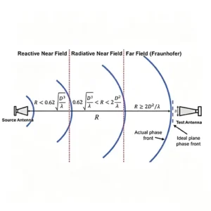
Table of Contents
- Introduction
- What Are the Near Field and Far Field of an Antenna?
- Why Can’t We Simply Use 3–5 Wavelengths?
- The Three Antenna Field Regions
- How to Calculate the Far-Field Distance
- What Happens With Large Antennas?
- Can an Antenna Be Tested in the Near Field?
- Near Field vs Far Field: What Is the Practical Difference?
- Near-Field and Far-Field Applications
- Why Does the Near Field Matter in Antenna Design?
- Is Near Field Better Than Far Field?
- Final Takeaway
Introduction
How far does an antenna need to be before it is considered to be in the far field?
You may have heard a simple rule: “Once the distance reaches a few wavelengths, the antenna is in the far field.” That rule can sometimes be a useful rough guide for electrically small antennas, but it is not a universal standard.
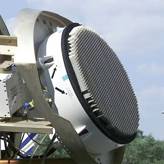
For a physically large antenna, the far-field distance can be much greater than a few wavelengths. A large phased-array antenna, for example, may require tens or even hundreds of meters before its far-field characteristics become stable.
The key is that far-field distance depends not only on wavelength, but also on the physical size of the antenna.
So what exactly happens between the antenna and the far field? To understand that, we need to look at the three main field regions around an antenna.
I. What Are the Near Field and Far Field of an Antenna?
The electromagnetic field around an antenna changes with distance.
Very close to the antenna, reactive fields can dominate and the field distribution can be strongly affected by the antenna structure and surrounding objects. Farther away, radiating fields become dominant and the angular radiation characteristics gradually become stable.
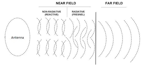
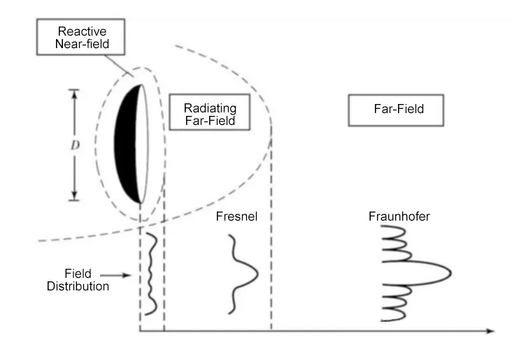
For many antennas, the surrounding space is commonly divided into three regions:
These regions do not represent three completely separate physical zones with sharp boundaries. The field characteristics change continuously with distance, while the boundaries provide useful engineering approximations for antenna analysis and measurement.
II. Why Can't We Simply Use 3–5 Wavelengths?
Wavelength is certainly important.
It can be calculated from: λ = c / f
λ is the wavelength, c is the speed of light, f is the operating frequency
For example, at 2.4 GHz: λ ≈ 0.125 m
A small Bluetooth or Wi-Fi antenna may have physical dimensions of only a few centimeters. Compared with the 12.5 cm wavelength, the antenna is electrically small.
For antennas of this type, a distance of several wavelengths may already be sufficient for many practical applications. However, the exact criterion depends on the antenna and the measurement requirement. Some antenna measurement references use approximately λ as a small-antenna far-field criterion, illustrating why a fixed “3–5 wavelengths” rule should not be treated as universal.
Now consider a much larger antenna operating at the same frequency.
If the antenna aperture is 0.5 m, the physical size is already several wavelengths across. The distance required for the far field is then governed strongly by the antenna aperture.
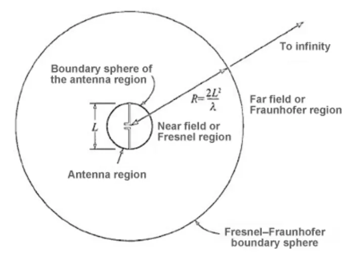
For electrically large antennas, the commonly used Fraunhofer distance is: R_FF ≈ 2D² / λ
where (D) is the maximum physical dimension of the antenna.
This is why two antennas operating at exactly the same frequency can have very different far-field distances. The wavelength tells us how long the electromagnetic wave is. The antenna dimension tells us how large a wavefront difference can develop across the antenna aperture.
III. The Three Antenna Field Regions
1. Reactive Near Field
The reactive near field is the region closest to the antenna. In this region, reactive electromagnetic fields play an important role. Energy can be stored temporarily in the electric and magnetic fields and exchanged with the antenna rather than simply propagating away as radiation.
This makes the region highly sensitive to the antenna’s surroundings. A nearby metal structure, another antenna, cable, PCB, battery, enclosure, or even a measurement probe can change the local electromagnetic field.
- For electrically large antennas, a commonly used approximation for the outer boundary of the reactive near field is: R_RNF ≈ 0.62 × √(D³ / λ)
- For very small antennas, however, different field-region criteria apply, so this expression should not be applied blindly.
This is also why an antenna can behave differently after it is installed inside a real product. An antenna that performs well on a laboratory fixture may experience a shift in impedance or resonant frequency after it is placed next to metal, a battery, or other RF components.
In other words: The reactive near field is where the antenna is most strongly influenced by its immediate electromagnetic environment.
2. Radiating Near Field
Farther away from the antenna, the radiating field becomes dominant. This region is called the radiating near field, or the Fresnel region.
Radiation is already propagating outward in this region, but the wavefront has not yet become sufficiently uniform across the observation region to produce a distance-independent angular radiation pattern.
For electrically large antennas, the radiating near field is commonly approximated as: 0.62 × √(D³ / λ) < R < 2D² / λ
In this region, the angular field distribution still depends on distance. As a result, measurements of radiation pattern characteristics can change as the measurement distance changes.
This does not mean that the radiating near field is useless. In fact, near-field measurement is an important antenna measurement technique. The difference is that engineers cannot simply take an unprocessed near-field pattern and treat it as the final far-field radiation pattern. Instead, near-field measurements can provide amplitude and phase information that can later be mathematically transformed into far-field characteristics.
3. Far Field
Once the observation distance is sufficiently large, the antenna enters the far field, also known as the Fraunhofer region.
For a sufficiently large distance: R_FF ≳ 2D² / λ, the electromagnetic field can be approximated as a locally plane wave.
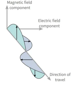
In the far field, the electric field and magnetic field are approximately perpendicular to each other and to the direction of propagation, with the free-space wave impedance approaching approximately 377 Ω. The field amplitude decreases approximately as 1/R1/R, while the average power density decreases approximately as 1/R21/R^2.
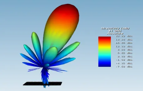
The most important practical feature is this: The angular radiation pattern becomes essentially independent of distance.
That means characteristics such as Main beam, Beamwidth, Sidelobes, Nulls, Front-to-back ratio and Polarization characteristics can be evaluated without the pattern changing simply because the observation distance has been slightly increased.
This is why far-field conditions are so important for many antenna measurements.
IV. How to Calculate the Far-Field Distance
For an electrically large antenna, the most commonly used estimate is: R_FF ≈ 2D² / λ
where RFF = far-field starting distance
D = maximum physical dimension of the antenna
λ = operating wavelength
Since λ = c / f, we can also write R_FF ≈ 2D²f / c
This equation immediately shows why antenna size matters so much. Because R_FF ∝ D², doubling the antenna’s maximum dimension increases the theoretical far-field distance by approximately four times.
A 10 GHz Phased-Array Example
Consider a phased-array antenna with Maximum dimension D=0.5 m, Operating frequency f=10 GHz.
The wavelength is approximately: λ = (3 × 10⁸) / (10 × 10⁹) = 0.03 m
Now calculate the far-field distance: R_FF = 2(0.5)² / 0.03 ≈ 16.7 m
So the theoretical far-field boundary is approximately 16.7 m
This does not mean that the antenna suddenly changes from near field to far field at exactly 16.7 m. It means that around this distance and beyond, the far-field approximation becomes appropriate according to this commonly used criterion.
In a high-accuracy measurement system, engineers may choose additional distance or use another test method depending on the required phase error, chamber geometry, calibration and measurement uncertainty.
V. What Happens With Large Antennas?
This relationship becomes even more important for large antenna apertures.
For example, keeping the same 10 GHz operating frequency:
Antenna Size | Approx. Far-Field Distance |
0.5 m | 16.7 m |
1 m | 66.7 m |
2 m | 266.7 m |
3 m | 600 m |
The numbers grow very quickly because the far-field distance depends on D2D^2.
This creates a practical problem. Imagine trying to measure a 2 m or 3 m high-frequency phased array in a conventional far-field range. The required distance can become hundreds of meters.
That is why large radar antennas, phased arrays and other large-aperture antennas often use specialized measurement techniques instead of simply moving the receiving antenna farther away.
VI. Can an Antenna Be Tested in the Near Field?
Yes. This is one of the most important points to understand.
Near-field measurement does not mean that the final result has to remain a near-field result. A near-field measurement system can scan an antenna with a probe and measure the electromagnetic field at many known positions. The system can record the complex field information, including amplitude and phase, across the measurement surface. Algorithms can then transform those near-field measurements into far-field radiation characteristics.
This process is called: Near-Field to Far-Field Transformation, or NF-to-FF.
- NASA describes near-field antenna measurement systems in which a probe scans a defined surface, records complex field data, and then uses near-field-to-far-field transformation algorithms to obtain the far-field pattern.
- Commercial antenna test systems also use this approach when a device is too large to satisfy practical far-field conditions within a compact test chamber.
So the correct way to think about it is measure the field where the test system can accurately sample it, then mathematically determine the far-field performance.
VII. Near Field vs Far Field: What Is the Practical Difference?
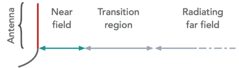
The easiest way to understand the three regions is to focus on what changes as the distance increases.
Region | Main Characteristic | Does the Angular Pattern Depend on Distance? |
Reactive Near Field | Reactive/stored-field effects are significant | Yes |
Radiating Near Field | Radiation dominates, but wavefront curvature remains important | Yes |
Far Field | Radiation field dominates and plane-wave approximation applies | Essentially no |
The boundaries are engineering approximations, not physical walls. The transition from one region to another is gradual.
VIII. Near-Field and Far-Field Applications
Understanding these regions becomes much more useful when we look at real RF systems.
Near-Field Applications
Near-field operation is particularly useful when a system needs short-range, controlled electromagnetic coupling.
A smartphone can communicate with a compatible terminal when the two devices are brought very close together. The short operating distance is part of the system design rather than a limitation that engineers are simply trying to overcome.
This type of local electromagnetic coupling is useful for applications such as contactless payment, access control and short-range identification.

RFID also needs some clarification here. Not all RFID operates in the near field.Different RFID systems use different frequency bands and coupling mechanisms. This distinction matters when selecting an RFID antenna.
- LF and HF RFID systems commonly rely on near-field coupling.
- UHF RFID systems generally use radiated electromagnetic waves for longer-range tag communication.
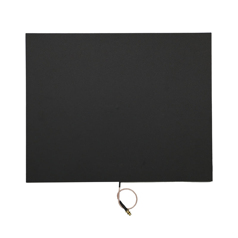
A near-field UHF RFID antenna is designed to create a controlled short-range reading zone rather than simply maximize reading distance. For example, Airplux offers UHF near-field RFID antennas for applications where controlled item-level reading is important, including shelves, cabinets and other space-constrained environments.
The goal in these applications is often not “read as far as possible.” Instead, the goal may be: Read the intended tag, within the intended area, while minimizing unwanted reads outside that area.
Far-Field Applications
Far-field radiation is fundamental to many wireless systems where electromagnetic energy propagates through space.
Wi-Fi and Wireless Networking
Directional Wi-Fi antennas are commonly designed to concentrate RF energy into a defined coverage area.
For example, a high-gain 5 GHz panel antenna uses a directional radiation pattern to concentrate energy rather than radiating uniformly in all directions. Airplux’s 5 GHz MIMO panel antenna series is one example of this type of directional design.
The important parameters are not only gain, but also beamwidth, polarization, radiation pattern and installation direction.
A higher-gain antenna generally concentrates energy into a narrower angular region, which is useful when the intended communication path is relatively well defined.

UHF RFID
Many UHF RFID reader antennas also operate primarily through far-field radiation.
In warehouse portals, logistics gates, manufacturing lines and asset-tracking systems, the reader antenna sends RF energy into a defined reading area, and tags communicate through backscatter.
Antenna gain, polarization, beamwidth, mounting angle and the surrounding environment all affect the resulting read zone.
This is why two UHF RFID antennas with the same operating frequency can behave very differently in a real installation.

Radar and Phased Arrays
Radar systems and phased-array antennas are another important example.
During operation, the antenna may direct electromagnetic energy toward a target or coverage area. During development and testing, engineers may characterize the antenna’s near-field distribution and use near-field-to-far-field transformation to calculate the far-field radiation characteristics.
For large arrays, this approach can be much more practical than building an extremely long far-field test range.
IX. Why Does the Near Field Matter in Antenna Design?
Near-field behavior is not only a testing issue. It also matters during antenna design and product integration.
Consider a compact antenna installed inside an electronic device. The antenna may be surrounded by a PCB, battery, metal housing, display, cables, other antennas and mechanical components. These objects can alter the electromagnetic environment around the antenna.
As a result, the antenna’s resonance, impedance, efficiency and radiation performance may change after installation, where nearby antennas can also introduce electromagnetic coupling.
For engineers, understanding the near field helps explain why an antenna that performs well by itself may behave differently after it is integrated into the final product.
X. Is Near Field Better Than Far Field?
Neither is inherently better. Near field and far field describe different electromagnetic conditions.
- A near-field system can be exactly what an application requires when it needs short-range, controlled coupling.
- A far-field system is appropriate when electromagnetic energy needs to propagate through space and the antenna’s directional radiation characteristics matter.
The important question is Which field behavior does this application require?
That distinction is especially important when selecting RFID, Wi-Fi, cellular, IoT or other RF antennas.
Final Takeaway
The common idea that “a few wavelengths means far field” is useful only as a rough intuition and should not be treated as a universal antenna rule.
For an electrically large antenna, a widely used far-field estimate is:
R_FF ≈ 2D² / λ
This relationship explains why large-aperture antennas can require surprisingly long test distances.
Before the far-field region, the antenna may pass through a reactive near-field region and a radiating near-field region. In these regions, the electromagnetic field and angular radiation characteristics can still depend strongly on distance.
But near-field measurement is not a dead end.
By measuring amplitude and phase over a suitable near-field scan surface and applying Near-Field to Far-Field Transformation, engineers can obtain far-field radiation characteristics without requiring an enormous test range.
You may also like
Master VSWR vs Return Loss — how they indicate mismatch, reflected power, and why both matter in RF antenna systems.

Learn what antenna gain means, how gain relates to directivity and efficiency, how dBi and dBd differ, and how to Choose the Right Gain.

Learn what return loss means, how it is calculated, and how it relates to S11, VSWR, impedance matching, and antenna performance.

Explore the trade-offs between power handling, transmission loss, coaxial design, and system compatibility.
Contact
We are always ready to serve you.
Please feel free to contact us
for any antenna inquiry or requirement.
Leave us a message in the form below and
we will get back to you within 24 hours.