
Antenna Gain Explained: Definition, dBi, dBd and How to Choose the Right Gain
Antenna Gain Explained: Definition, dBi, dBd and How to Choose the Right Gain
Table of Contents
- Introduction
- What Is Antenna Gain?
- Antenna Gain Does Not Mean Power Amplification
- Gain, Directivity and Efficiency: What Is the Difference?
- Antenna Gain Is Directional
- Why Higher Gain Usually Means Narrower Coverage
- Why an Antenna Can Have Negative Gain
- dBi vs. dBd: What Is the Difference?
- How Antenna Size Affects Gain
- Does Higher Frequency Always Mean Higher Gain?
- Polarization Also Matters
- Antenna Gain and EIRP
- Why Gain Alone Is Not Enough When Choosing an Antenna
- How to Choose the Right Antenna Gain
- Gain Is Only One Part of Antenna Performance
- Final Thoughts
Introduction
When engineers compare antennas, gain is often one of the first specifications they look at.
A 5 dBi antenna, a 10 dBi antenna, and a 15 dBi antenna may appear to be three simple numbers on a datasheet. It is tempting to assume that the higher the number, the stronger the antenna and the better the wireless link will be.
That is not quite how antenna gain works.
An antenna does not create RF energy like a power amplifier. It is a passive device that controls how electromagnetic energy is distributed through space. A higher gain generally means that more of the available radiated energy is concentrated in a particular direction, usually at the expense of wider angular coverage.
Understanding this distinction is important when selecting antennas for Wi-Fi, cellular networks, RFID, IoT, microwave links, satellite communications, radar, and other RF systems.
This article explains what antenna gain means, how it relates to directivity and efficiency, why dBi and dBd are different, and why higher gain is not always better.
I. What Is Antenna Gain?
Antenna gain describes how strongly an antenna radiates or receives electromagnetic energy in a particular direction compared with a reference isotropic radiator.
An isotropic radiator is an ideal reference that radiates equally in every direction. It does not represent a practical antenna; instead, it provides a standardized reference for comparing antenna performance.
When antenna gain is expressed relative to this isotropic reference, the unit is dBi, or decibels relative to isotropic.
For example, a 10 dBi antenna has a power ratio of 10 in its maximum-gain direction compared with an ideal isotropic radiator under the corresponding reference conditions. The important point is that this does not mean that the antenna has created ten times more RF power. It means that the antenna produces a higher power density in that direction by distributing the available energy more selectively through space.
This is why a directional antenna can improve the strength of a wireless link without increasing transmitter output power.
Think of gain as energy concentration, a simple analogy is a flashlight.
A bare light source spreads light over a wide area. Add a reflector or lens, and the same available energy can become much more concentrated in one direction. The illuminated area becomes smaller, but the light intensity in that direction increases. An antenna works according to a similar principle. A directional antenna concentrates electromagnetic energy into a smaller angular region. The result is higher gain in that region, while other directions receive less radiation.
This is also why a high-gain antenna is not automatically a better antenna for every application.
II. Antenna Gain Does Not Mean Power Amplification
One of the most common misunderstandings is treating antenna gain like amplifier gain. A power amplifier increases RF power by using an external energy supply. An antenna does not.
For a practical antenna, some input power is lost through mechanisms such as conductor loss and dielectric loss. The remaining available power is converted into electromagnetic radiation and distributed according to the antenna’s radiation pattern. The gain describes how strongly that radiation is concentrated relative to the reference antenna.
In other words:
A power amplifier adds RF power to the signal.
An antenna gain redistributes available RF energy spatially.
This distinction becomes especially important when designing a complete RF system.
Suppose two transmitters use the same 10 W output power. One uses a low-gain omnidirectional antenna and the other uses a high-gain directional antenna. The second system does not suddenly have a 10 W transmitter plus additional RF energy. Instead, more of the available radiated energy is concentrated toward the intended direction.
That directional concentration can increase the received signal level and extend the useful communication range, provided that the antennas are properly aligned and the rest of the link budget supports it.
III. Gain, Directivity and Efficiency: What Is the Difference?
Antenna gain is closely related to two other important parameters: directivity and efficiency. Directivity describes how concentrated an antenna’s radiation pattern is, without accounting for the losses inside the antenna. Gain takes those losses into account.
The relationship can be written as: G = ηD
- G is antenna gain
- D is directivity
- η is antenna radiation efficiency
In decibel form: G(dBi) = D(dBi) + 10 log₁₀(η)
For a perfectly efficient antenna, η = 1, so gain and directivity are equal. For a real antenna, efficiency is generally below 100%, so gain is lower than directivity. Conductor losses, dielectric losses and losses in the antenna structure can all reduce the amount of input power that becomes radiation.
This relationship explains why two antennas with similar physical dimensions can have different gains. The difference may come not only from their radiation patterns, but also from their efficiency.
A simple example
Imagine an antenna with a directivity of 10 dB and a radiation efficiency of 80%.
The linear efficiency is: η = 0.8, therefore: G = 0.8 × D
In dB, the 80% efficiency introduces a loss of about 0.97 dB, so the antenna gain is approximately 9.03 dBiIf the efficiency falls to 50%, the efficiency loss becomes about 3 dB, and the gain drops accordingly.
This is why improving the radiation efficiency can be just as important as improving the radiation pattern.
IV. Antenna Gain Is Directional
Another important point is that antenna gain is not the same in every direction.
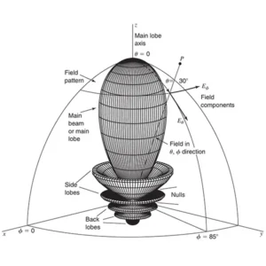
A directional antenna may have high gain in the main-beam direction and much lower gain at the sides or rear. The radiation pattern shows how the antenna’s gain changes with angle.
The direction of maximum radiation is called the main beam or main lobe. Other radiation regions are commonly referred to as sidelobes and backlobes. Nulls may also appear at certain angles where the radiation becomes very low.
When a datasheet gives one gain value, such as 12 dBi, it normally refers to the antenna’s maximum or peak gain, unless another definition is specified. That number alone therefore does not describe the entire antenna pattern. Two antennas can both be rated at 12 dBi and still behave very differently. One may have a relatively wide beam suitable for area coverage, while another may have a much narrower beam intended for point-to-point communication.
For this reason, gain should always be considered together with horizontal beamwidth, vertical beamwidth, radiation pattern, sidelobe level and front-to-back ratio where applicable.

V. Why Higher Gain Usually Means Narrower Coverage
There is a practical trade-off between gain and angular coverage. When an antenna concentrates more energy into a smaller angular region, the power density in that region increases. In many directional antennas, this corresponds to a narrower beamwidth.
This is why high-gain antennas are commonly used for applications where the communication path is known and relatively fixed.
A parabolic antenna, for example, can concentrate energy into a very narrow beam for satellite or microwave links.By contrast, an omnidirectional antenna distributes radiation over a much wider area in the horizontal plane. It generally provides broader angular coverage but less directional concentration.
The right question is therefore not: “Which antenna has the highest gain?”
It is: “How much gain do I need for the coverage pattern and link direction I actually have?”
For a warehouse, a 360° wireless system may need broad coverage rather than extremely high gain. For a point-to-point microwave link, a narrow high-gain beam may be exactly what the application requires.

VI. Why an Antenna Can Have Negative Gain
It is also worth clearing up a common misconception: antenna gain is not necessarily a positive number.
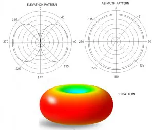
Gain can be negative, particularly for electrically small or inefficient antennas. In addition, gain is a function of direction, so some directions in an antenna’s radiation pattern can have very low gain. This is another reason why statements such as “all practical antennas have positive dBi” are inaccurate.
The important value on a product datasheet is usually the peak gain, but the complete radiation behavior requires looking at the antenna pattern rather than focusing on one number alone.
VII. dBi vs. dBd: What Is the Difference?
Two units commonly appear in antenna specifications: dBi and dBd.
The difference is the reference antenna:
- dBi means decibels relative to an ideal isotropic radiator.
- dBd means decibels relative to a half-wave dipole.
A half-wave dipole has approximately 2.15 dBi of gain relative to an isotropic radiator. Therefore: Gain (dBi) ≈ Gain (dBd) + 2.15
For example:
- 0 dBd ≈ 2.15 dBi
- 5 dBd ≈ 7.15 dBi
- 8 dBd ≈ 10.15 dBi
When comparing products from different manufacturers, always check whether the stated gain uses dBi or dBd. Comparing the numbers directly without checking the reference can lead to the wrong conclusion.

VIII. How Antenna Size Affects Gain
Antenna size is strongly related to achievable gain, especially for aperture and array antennas. At the same operating frequency, increasing the effective aperture generally makes it possible to produce a narrower beam and higher directivity.
This is easy to see with parabolic antennas.
A larger reflector can collect and focus electromagnetic energy more effectively, producing higher directivity and typically higher gain.
But antenna size does not provide a free performance upgrade. Larger antennas may increase weight, wind load, mechanical complexity, installation requirements and cost. For an antenna mounted on a tower, vehicle or building, these engineering constraints can become just as important as the RF specification.
The useful design target is therefore not simply “maximum gain,” but the required gain within the available physical and mechanical limits.
IX. Does Higher Frequency Always Mean Higher Gain?
Does Higher Frequency Always Mean Higher Gain?
Frequency and gain are related, but the relationship is more subtle than “higher frequency means higher gain.”
What matters is the antenna’s electrical size, which describes its physical dimensions relative to wavelength.
As frequency increases, wavelength becomes shorter. A physically unchanged antenna therefore becomes electrically larger, which can allow greater directivity in some antenna structures.
However, antenna gain also depends on geometry, efficiency, matching, bandwidth, materials, feeding structure and operating mode. A design that performs well at one frequency cannot simply be assumed to have proportionally higher gain at another frequency.
This is particularly important for broadband antennas and multiband products. Engineers should evaluate gain across the actual operating frequency range rather than relying on a single frequency-based assumption.
X. Polarization Also Matters
Gain alone does not determine how much power a receiving system will obtain. The transmitting and receiving antennas must also have compatible polarization.
For example, a vertically polarized transmitting antenna and a horizontally polarized receiving antenna can suffer severe polarization mismatch. The same principle applies to circularly polarized systems, where the polarization sense must also be considered.
An ideal linearly polarized antenna receiving a wave polarized orthogonally to it can theoretically receive zero power because of complete polarization mismatch.
For circular and linear polarization, the mismatch behavior is different and should not be reduced to a universal “3–6 dB” rule.
In practical systems, polarization mismatch, cross-polarization, antenna orientation and installation conditions can all affect the effective received signal. So when evaluating antenna performance, engineers should look at gain and polarization together, especially in RFID, satellite communications, GNSS, radar and other polarization-sensitive applications.
XI. Antenna Gain and EIRP
Antenna gain becomes particularly important when calculating the radiated performance of a wireless system.
A simplified EIRP relationship is:
EIRP (dBm) = Transmitter output power (dBm) − Feeder losses (dB) + Antenna gain (dBi)
For example, assume a transmitter delivers 20 dBm to the antenna, the feeder and connector losses total 2 dB, and the antenna has 10 dBi gain.
Then: EIRP = 20 − 2 + 10 = 28 dBm
The antenna has not increased the transmitter’s electrical output power. Instead, its directional gain increases the equivalent isotropic radiated power in the direction of maximum radiation.
This concept is widely used in wireless link budgets and in regulatory calculations. It also explains why antenna gain and transmitter power should be considered together rather than evaluated separately.
XII.Why Gain Alone Is Not Enough When Choosing an Antenna
Imagine that you are comparing two 10 dBi antennas.
At first glance, they appear equivalent. But one might have a 60° horizontal beamwidth while the other has a 25° beamwidth. One could be designed for broad area coverage, while the other is intended for a narrow directional link.
They may also differ in:
- Operating frequency and bandwidth
- Polarization
- VSWR
- Radiation efficiency
- Front-to-back ratio
- Side-lobe level
- Connector configuration
- Environmental protection
- Physical dimensions and mounting options
These parameters can significantly change how the antennas perform in the real world. This is why a good antenna selection process starts with the application, not the gain number.
XIII. How to Choose the Right Antenna Gain
The first question should be: What kind of coverage do you need?
- For broad or omnidirectional coverage, a moderate-gain antenna may be more appropriate because the system needs to serve users or devices across a wider angular region.
- For fixed point-to-point communication, a higher-gain directional antenna may provide a better link by concentrating energy toward the remote endpoint.
- For RFID, the situation is different again. Antenna gain, polarization, read-zone geometry, reader power, tag orientation and the surrounding environment all affect read performance. A higher-gain antenna is not automatically the best choice for every RFID installation.
The same principle applies to Wi-Fi, cellular, LoRa, GNSS and other wireless systems. The goal is to match the antenna’s gain, beamwidth, polarization and radiation pattern to the actual deployment environment.
XIV. Gain Is Only One Part of Antenna Performance
Antenna gain is an important specification, but it should never be considered in isolation.
A useful way to evaluate an antenna is to look at the complete picture:
- Gain tells you how strongly energy is concentrated.
- Beamwidth tells you how wide that concentration is.
- Radiation pattern tells you where the energy goes.
- Efficiency tells you how effectively input power is converted into radiation.
- Polarization tells you how the electromagnetic field is oriented.
- VSWR and impedance tell you how well the antenna interfaces with the RF system.
Together, these parameters provide a much more realistic picture of antenna performance than gain alone.
Final Thoughts
Higher gain is not always better.
Antenna gain is often reduced to a single number on a product datasheet, but the engineering concept behind that number is much richer.
Gain does not mean that an antenna creates RF power. It describes how effectively the antenna concentrates available radiation in a particular direction compared with a reference isotropic radiator.
Higher gain can improve link performance, but it normally comes with greater directionality and a narrower coverage area. Lower gain can be the better engineering choice when a system needs wide-area coverage or greater tolerance to changing device locations.
For this reason, the best antenna is not necessarily the one with the highest gain.
It is the antenna whose gain, beamwidth, radiation pattern, polarization, efficiency, frequency range and physical design match the application.
Once you understand that principle, an antenna datasheet becomes much easier to read—and the gain number starts to tell you much more than it first appears to.
You may also like
This article is about the Antenna Radiation Patterns Explained, it contain a Visual Guide to 85 Antenna Types.

Learn what antenna efficiency means, how radiation and total efficiency differ, and how VSWR and gain affect antenna performance.
Learn what is antenna polarization, its types, importance, and applications in modern wireless communication systems.
Contact
We are always ready to serve you.
Please feel free to contact us
for any antenna inquiry or requirement.
Leave us a message in the form below and
we will get back to you within 24 hours.