
VSWR vs. Return Loss: What’s the Difference and Why Does It Matter?
VSWR vs. Return Loss: What’s the Difference and Why Does It Matter?

Table of Contents
- Introduce
- What Causes RF Power to Reflect?
- What Is VSWR?
- What Is Return Loss?
- How Are VSWR and Return Loss Related?
- Does Reflected Power Mean the Antenna Is Not Working?
- Why Does VSWR Matter in Antenna Systems?
- What Can Cause High VSWR?
- How Do Engineers Measure VSWR and Return Loss?
- VSWR and Return Loss: Which One Should You Use?
- A Practical Example
- Don’t Judge an Antenna by VSWR Alone
- Final Takeaway
Introduction
When engineers evaluate an RF antenna, two specifications often appear together: VSWR and Return Loss.
Both describe the quality of impedance matching in an RF system, but they express the same underlying phenomenon in different ways. Understanding the relationship between them can help engineers evaluate antenna performance, identify installation problems, and determine whether RF power is being delivered efficiently to the antenna.
So, what actually happens when an antenna is not properly matched? The short answer is simple: some of the RF power is reflected back toward the transmitter instead of being delivered to the antenna.
To understand VSWR and Return Loss, it helps to start with impedance matching.
⭐A Return Loss ⇄ VSWR Calculator is also included at the end of this article, allowing you to quickly convert between the two values.
I. What Causes RF Power to Reflect?
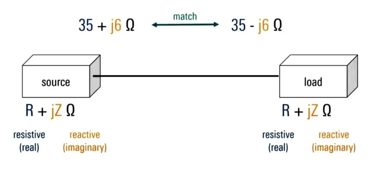
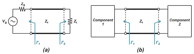
Most RF systems are designed around a characteristic impedance of 50 ohms. A typical signal path may include a transmitter, coaxial cable, connectors, and an antenna. Ideally, each part should present a compatible impedance to the next part of the system. When the antenna impedance differs from the characteristic impedance of the transmission line, part of the incident RF wave reflects back toward the source.
For example, consider a system with a 50-ohm transmitter and a 50-ohm coaxial cable connected to an antenna whose impedance is not properly matched to 50 ohms. The cable itself may be perfectly fine, but the impedance discontinuity at the antenna creates a reflection.
This is the fundamental principle: Impedance mismatch → reflection → less power delivered to the load.
The severity of that reflection depends on how large the mismatch is.
This is why antenna specifications commonly include VSWR or Return Loss. They give engineers a way to quantify the mismatch.

II. What Is VSWR?
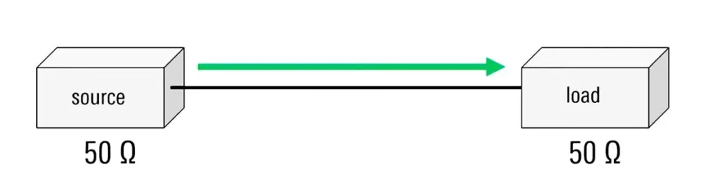
VSWR, or Voltage Standing Wave Ratio, describes the standing-wave behavior that occurs when an incident RF wave and a reflected wave interact along a transmission line.
The ideal VSWR is 1:1. This represents a perfectly matched load, where no power reflects back from the load. As the impedance mismatch increases, VSWR increases.
A VSWR of 1.2:1 therefore represents a better impedance match than 2.0:1. However, it is important not to label a particular VSWR value as universally “good” or “bad.” The acceptable value depends on the requirements of the RF system.
For example, an antenna specification may state VSWR ≤ 1.5, while another application may allow VSWR ≤ 2.0. The requirement depends on factors such as operating frequency, transmitter power, system design, and application.
The basic rule is: Lower VSWR means better impedance matching.
VSWR is particularly useful when engineers are checking antenna specifications or testing an installed RF system because it provides an intuitive ratio for describing mismatch.
III. What Is Return Loss?
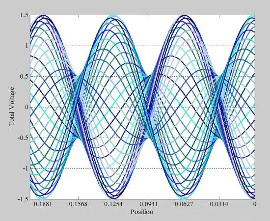
Return Loss (RL) expresses the amount of reflected signal in decibels (dB).
Unlike VSWR, where a value closer to 1 is better, Return Loss follows the opposite direction: a higher positive Return Loss indicates a better impedance match.
For example, a Return Loss of 20 dB represents a smaller reflection than a Return Loss of 10 dB.
This happens because Return Loss relates directly to the magnitude of the reflection coefficient. In simplified form:
Return Loss = −20 log₁₀ |Γ|
where Γ is the reflection coefficient.
A perfectly matched system has a reflection coefficient of zero, which corresponds theoretically to infinite Return Loss.
This gives us an important distinction: VSWR asks how large the standing-wave ratio is, while Return Loss tells us how small the reflected wave is in dB.
They describe the same mismatch from different perspectives.
IV. How Are VSWR and Return Loss Related?
VSWR and Return Loss are not independent measurements of two unrelated problems. Both derive from the reflection coefficient.
The relationship can be expressed as:
VSWR = (1 + |Γ|) / (1 − |Γ|)
Return Loss = −20 log₁₀ |Γ|
Because both parameters depend on the same reflection coefficient, you can convert one into the other.
For example, a VSWR of approximately 1.22:1 corresponds to a Return Loss of about 20 dB. A VSWR of 1.5:1 corresponds to approximately 14 dB Return Loss, while a VSWR of 2.0:1 corresponds to approximately 9.5 dB.
The relationship looks like this:
VSWR | Approx. Return Loss | Reflected Power |
1.2:1 | 20.8 dB | 0.83% |
1.5:1 | 14.0 dB | 4.0% |
2.0:1 | 9.5 dB | 11.1% |
3.0:1 | 6.0 dB | 25.0% |
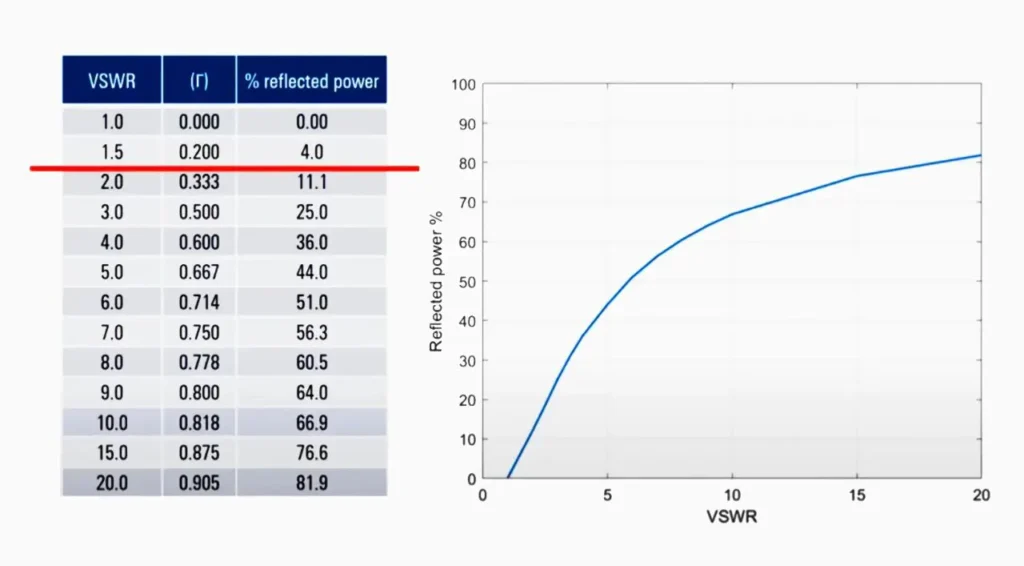
This table also reveals an important point: a seemingly modest change in VSWR can represent a significant change in reflected power.
For instance, a VSWR of 2.0:1 corresponds to about 11% reflected power under a steady-state single-frequency condition, not 50%.
That distinction matters when evaluating antenna performance.
V. Does Reflected Power Mean the Antenna Is Not Working?
Not necessarily.
An antenna with a non-perfect impedance match can still radiate RF energy. The issue is that not all of the available incident power reaches the antenna load.
For example, if 100 W of incident power reaches a load with a VSWR of 2.0:1, the reflected power associated with the mismatch is approximately 11.1 W, assuming the measurement is made at the relevant reference plane and there are no other losses being included. The remaining incident power is delivered to the load.
However, impedance mismatch is only one part of overall RF system efficiency. Cable loss, connector loss, antenna efficiency, polarization mismatch, installation conditions, and other factors can also affect the final radiated power.
This is why VSWR should not be treated as a direct measurement of antenna gain or radiation efficiency.
A low VSWR does not automatically mean an antenna has high gain, and a high-gain antenna does not necessarily have the lowest possible VSWR.
VI. Why Does VSWR Matter in Antenna Systems?
For antenna engineers, VSWR is important because impedance matching affects how effectively an RF transmitter can deliver power to the antenna. A significant mismatch can reduce the power delivered to the antenna and increase reflected power toward the transmitter.
In high-power RF systems, excessive reflected power can also increase stress on RF components such as power amplifiers. Many modern transmitters include protection mechanisms that reduce output power when they detect excessive reflected power.
In wireless infrastructure, a poor match can therefore contribute to reduced system performance. However, engineers should not automatically blame the antenna whenever VSWR is high. The problem may originate somewhere else in the RF path.
VII. What Can Cause High VSWR?
A high VSWR measurement does not necessarily mean that the antenna itself has a design problem.
The entire RF path needs to be considered.
A damaged or poorly terminated coaxial cable can create impedance discontinuities. A loose connector, incorrect connector assembly, moisture entering an outdoor connection, or an excessive cable bend can also affect the RF path.
The operating frequency matters as well.
An antenna designed for one frequency range may show excellent VSWR within its specified band but significantly worse performance outside that range. This is why engineers should always compare the measured VSWR with the antenna’s specified frequency range.
Installation conditions can also influence antenna impedance. Nearby metal structures, mounting brackets, cables, enclosures, and other objects can alter the electromagnetic environment around an antenna and change its measured performance.
For outdoor systems, water ingress is another common concern. Moisture around connectors or inside damaged cables can introduce additional losses and impedance discontinuities.
In practice, troubleshooting should therefore follow the entire RF chain rather than focusing on the antenna alone.
VIII. How Do Engineers Measure VSWR and Return Loss?
Engineers commonly use instruments such as vector network analyzers (VNAs), antenna analyzers, and cable-and-antenna analyzers to evaluate impedance matching.
For installed communication systems, a cable-and-antenna analyzer or site-testing instrument can sweep the required frequency range and show parameters such as VSWR, Return Loss, and reflection coefficient.
A typical troubleshooting process starts with a frequency sweep. If the measured result does not meet the expected specification, the engineer can then inspect connectors, cables, adapters, and the antenna installation.
The key is to determine where the mismatch occurs, rather than simply observing that a high VSWR exists.
For example, if an antenna has a specified VSWR of ≤1.5 within its operating band but the installed system measures 2.5:1, engineers should investigate the complete RF path before concluding that the antenna is defective.
IX. VSWR and Return Loss: Which One Should You Use?
There is no need to choose one as the “better” parameter.
Both are useful because they present the same impedance-matching behavior in different formats.
VSWR is often easy to interpret when reviewing antenna specifications, while Return Loss is widely used in RF measurement and network analysis because it expresses reflection on a logarithmic dB scale.
In many engineering environments, both values appear in test reports or measurement equipment. What matters most is understanding what the numbers mean and comparing them against the requirements of the particular RF system.
A useful way to remember the relationship is:
Lower VSWR = less mismatch
Higher Return Loss = less reflection
X. A Practical Example
Suppose an antenna operates at 915 MHz and the measured VSWR is 1.5:1.
A VSWR of 1.5:1 corresponds to a Return Loss of approximately 14 dB and a reflected-power fraction of about 4%.
This does not mean that 4% of the total system power is automatically lost in every practical installation. It represents the portion of the incident power reflected by the impedance mismatch at the measurement reference plane. Other losses in cables, connectors, and the antenna itself are separate considerations.
This distinction is especially important when analyzing real-world RF systems.
XI. Don't Judge an Antenna by VSWR Alone
VSWR is an important antenna specification, but it should never be evaluated in isolation.
When selecting an antenna, engineers normally need to consider several parameters together, including frequency range, gain, radiation pattern, polarization, beamwidth, impedance, VSWR, connector type, power handling, and environmental protection.
For example, an antenna with a VSWR of 1.5:1 may be perfectly suitable for one application, while another system may require a tighter impedance match.
Similarly, improving VSWR does not necessarily improve every other antenna characteristic. Antenna design always involves balancing multiple electrical and mechanical requirements.
The right question is therefore not simply: What is the lowest VSWR?
It is: Does the antenna provide the required impedance match and overall RF performance across the operating band?
Final Takeaway
VSWR and Return Loss provide two ways to understand impedance mismatch and RF reflection.
- VSWR uses a ratio, with 1:1 representing a perfect match and lower values indicating less mismatch.
- Return Loss uses decibels, with higher positive values indicating less reflected power and a better match.
Both ultimately relate to the reflection coefficient.
When VSWR increases, Return Loss decreases, and the amount of reflected power increases. But a VSWR measurement alone cannot tell you the complete efficiency or performance of an antenna.
For engineers troubleshooting an RF system, the most useful approach is to look at the complete signal path—from the transmitter and cable to the connectors, antenna, and installation environment.
The goal is not simply to achieve a low VSWR. The goal is to deliver RF power efficiently and reliably to the antenna and achieve the required system performance.
You may also like

Learn what return loss means, how it is calculated, and how it relates to S11, VSWR, impedance matching, and antenna performance.

Why do RF systems use 50 ohm impedance? Explore the trade-offs between power handling, transmission loss, coaxial design, and system compatibility.

Learn what antenna efficiency means, how radiation and total efficiency differ, and how VSWR and gain affect antenna performance.
Contact
We are always ready to serve you.
Please feel free to contact us
for any antenna inquiry or requirement.
Leave us a message in the form below and
we will get back to you within 24 hours.