
Starlink Terminal Evolution: From Motorized Dishes to Compact Phased-Array Antennas
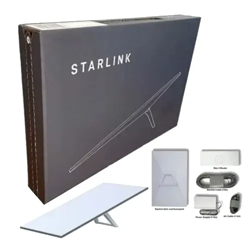
Starlink Terminal Evolution: From Motorized Dishes to Compact Phased-Array Antennas
Introduction
Starlink has changed how satellite internet reaches homes, vehicles, vessels, and remote locations. Instead of relying on a large parabolic dish that points toward a satellite, Starlink user terminals use electronically steered phased-array antennas to maintain communication with satellites moving across low Earth orbit.
The evolution of these terminals involves more than changes in shape or size. Each product stage reflects a different balance between antenna performance, mechanical complexity, power consumption, portability, and installation requirements.
From the original round terminal to rectangular residential hardware and the compact Starlink Mini, the product line illustrates how satellite communication equipment has adapted to different environments. Emerging vehicle-integration concepts also point toward a future in which communication hardware becomes part of a larger product rather than a separate external device.
This article explores the major stages of Starlink terminal evolution, the antenna technologies behind them, and the engineering considerations that shape their design. The stage labels used here are descriptive, not a claim that Starlink has published one universal generation numbering system covering every terminal. Product names such as Standard, Standard 4, Standard 4X, V4, and V5 should be interpreted in the context of the relevant official product documentation.
1. Why Starlink Terminals Have Evolved
Traditional satellite internet systems often use parabolic reflector antennas. These antennas concentrate radio-frequency energy toward a particular direction, providing the gain needed to communicate with satellites over long distances.
However, a reflector antenna must maintain a suitable physical orientation. Tracking moving satellites can require mechanical positioning systems, while mobile applications introduce additional challenges involving vibration, installation space, wind loading, and power availability.
Starlink takes a different approach by using electronically steered phased-array antennas. These antennas can change the direction of their main beam by adjusting the relative phases of signals across multiple radiating elements. This allows the terminal to track satellites without continuously rotating the antenna mechanically.
Electronic beam steering does not eliminate every design constraint. The terminal still needs sufficient antenna aperture, suitable RF electronics, thermal management, a clear view of the sky, and enough power to operate. Improving one characteristic can also affect another.
For example, reducing the antenna’s physical size can make a terminal easier to carry or integrate into a vehicle, but it can also reduce available aperture and affect link performance. Lower power consumption is valuable for battery-powered equipment, yet the design must still support the required transmission, reception, and processing functions.
These trade-offs explain the main direction of Starlink terminal development: adapting the same underlying satellite communication technology to increasingly diverse installation and operating conditions.
2. Early Terminal Designs: From Round to Rectangular
2.1 The Original Round Terminal
Early Starlink residential terminals introduced a flat antenna panel with an electronically steered phased array. Unlike a conventional satellite dish, the panel did not need to rotate continuously to follow each satellite.
The original round terminal also incorporated a motorized positioning mechanism. The motor helped orient the antenna assembly, while electronic beam steering handled satellite tracking within the array’s usable field of view.
This combination of mechanical positioning and electronic steering provided a practical way to balance installation flexibility with antenna performance.
The design nevertheless involved several physical components: the antenna panel, positioning mechanism, supporting structure, cabling, and associated electronics. Motors and moving parts also introduce additional mechanical complexity, weight, and potential maintenance requirements.
The original round terminal therefore represents an important early stage in the transition from mechanically pointed satellite antennas to flat, electronically steered user terminals.
2.2 The Rectangular Motorized Terminal
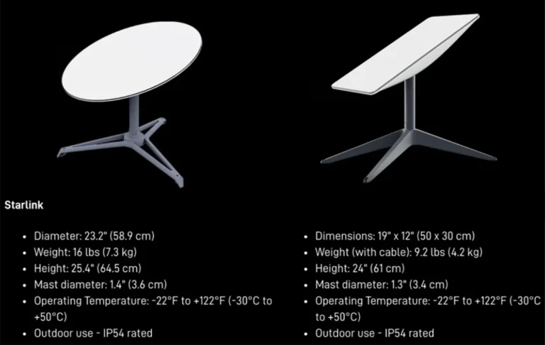
Later residential hardware adopted a rectangular antenna panel and continued to use electronic beam steering alongside motorized positioning in the actuated design.
A rectangular panel can be easier to package, transport, mount, and manufacture in standardized dimensions. Its shape also changes the distribution of the available antenna aperture in the horizontal and vertical directions, influencing the antenna’s directional characteristics.
However, a rectangular outline alone does not establish better RF performance. The result depends on the complete antenna design, including the radiating elements, their spacing, the feed network, the RF electronics, and the beamforming implementation.
The more important development was the continued refinement of the terminal as an integrated product. Antenna performance had to work together with the enclosure, positioning hardware, cabling, mounting accessories, and outdoor environmental protection.
These early designs established the foundation for later hardware that reduced mechanical complexity and supported a wider range of installation requirements. The labels “first generation” and “second generation” are commonly used to describe early product iterations, but they should not be treated as a universal official naming scheme for every Starlink terminal.
3. Reducing Mechanical Complexity: Software-Assisted Orientation
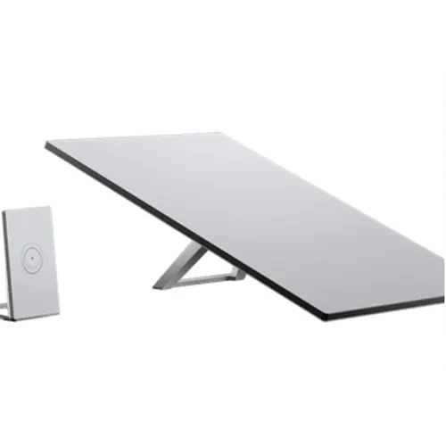
3.1 Standard Hardware and Electronic Beam Steering
A major design direction in Starlink’s later standard hardware is the reduction of dependence on motorized positioning.
Starlink’s published Standard specification lists an electronically steered phased-array antenna with a 110-degree field of view. The same specification identifies software-assisted manual orientation rather than a motorized automatic positioning system.
This distinction matters. Removing the motor does not mean removing electronic tracking. The user or installer establishes the antenna’s orientation, while the phased array electronically steers its beam to communicate with satellites within the available field of view.
Without a positioning motor, the terminal can avoid the associated mechanical assembly, moving-part wear, and motor power requirements. A simpler mechanical design may also make the product easier to package and maintain.
Nevertheless, a motorless terminal still needs a suitable mounting position. If the antenna cannot see enough of the sky because of buildings, trees, terrain, or other obstructions, electronic steering cannot compensate for every blocked satellite path.
In product discussions, some users refer to motorless Standard hardware as “Gen 3.” That label is commonly used but should be distinguished from the exact product names in Starlink’s current documentation. Standard, Standard 4, and Standard 4X are product labels whose meaning should be checked against the relevant model and market rather than assumed to correspond directly to a single universal generation sequence.
3.2 Why the Field of View Matters
The field of view describes the angular region over which an antenna can support its intended operation. It is an important design parameter because low Earth orbit satellites move rapidly across the sky from the terminal’s perspective.
A wider usable field of view can give the terminal more opportunities to communicate with satellites without physically repositioning the panel. It can also influence where installers can place the equipment.
However, field of view should not be confused with a guarantee of equal performance at every angle. As a phased array steers farther away from its surface normal, its effective projected aperture decreases, and its gain and radiation characteristics may change. Mutual coupling, element patterns, polarization performance, and array geometry also affect the usable scan range.
A published field-of-view figure therefore describes an important capability, but it does not independently establish the antenna’s gain, throughput, or link reliability at every direction.
4. Starlink Mini: Adapting the Terminal for Portability
Starlink Mini represents a different priority in terminal design: portability.
Compared with standard residential hardware, Mini uses a more compact enclosure intended to make satellite internet easier to carry and deploy in locations where a larger installation may be inconvenient. It is suited to use cases such as camping, temporary work sites, travel, and other situations where equipment size and power availability matter.
4.1 Smaller Size and Lower Power Requirements
Starlink’s published support specifications list average power consumption of approximately 20–40 W for Mini, compared with 75–100 W for Standard 4 and Standard 4X. Actual consumption varies with operating conditions and use.
Lower power consumption can simplify battery-based deployments and reduce the energy required during extended operation. Its compact form also reduces the amount of space needed for transport and installation.
These advantages do not mean Mini provides identical performance to every standard terminal under all conditions. Antenna aperture, available power, environmental conditions, network load, and satellite visibility all influence real-world performance.
Mini is best understood as a product optimized for a different set of priorities rather than simply a smaller replacement for every Starlink terminal.
4.2 Portability Changes the Installation Model
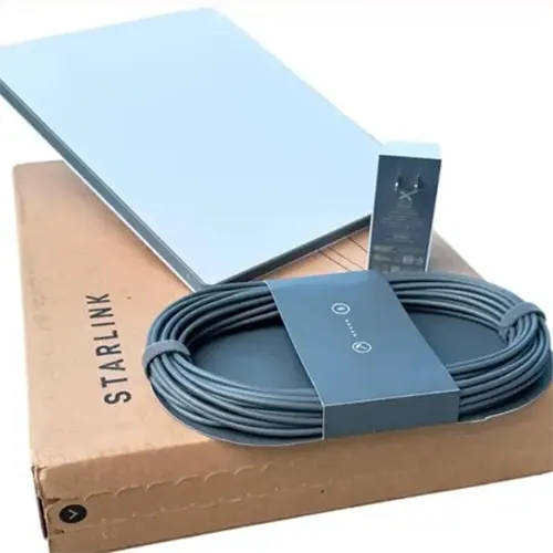
Traditional residential terminals are often installed in a relatively fixed location. A portable terminal needs to accommodate more varied surroundings, temporary mounting arrangements, and changing power sources.
That difference affects the entire product, not just the antenna panel. The enclosure, mounting method, cable arrangement, integrated electronics, and power interface all contribute to usability.
As a result, terminal evolution is not a single progression in which each new product replaces the previous one. Standard, portable, and higher-performance hardware can coexist because different applications require different compromises.
5. V4 versus V5: Published Specifications
Starlink’s official comparison identifies V4 and V5 as distinct terminal models with different physical dimensions, weight, power consumption, and published peak download speeds. These labels should be retained when discussing the comparison rather than automatically translating them into a universal “fourth-generation versus fifth-generation” classification.
| Parameter | V4 | V5 |
|---|---|---|
| Dimensions | 594 × 383 × 39.7 mm | 384 × 306 × 34 mm |
| Terminal weight | 2.9 kg | 1.1 kg |
| Average power consumption | 75–100 W | 35–50 W |
| Published peak download speed | 400+ Mbps | 375+ Mbps |
| Field of view | 110° | 110° |
The published figures show that V5 is substantially smaller and lighter than V4, with a lower stated average power-consumption range. However, the listed peak download speeds should not be interpreted as a direct measurement of antenna gain or RF performance. Actual throughput also depends on network conditions, service configuration, satellite availability, and the operating environment.
The comparison also illustrates why terminal naming and specification sources matter. Dimensions, weight, and power consumption can be compared directly as published, but a parameter should not be assumed identical across models simply because the terminals belong to the same product family. Where a model-specific specification is not confirmed, it is better to flag the gap than to fill it with an inferred value.
6. How Phased-Array Antennas Make Electronic Tracking Possible
To understand the technical significance of Starlink’s development, it helps to look at the antenna architecture itself.
6.1 From a Reflector to a Flat Antenna Array
A parabolic reflector uses its curved surface to concentrate electromagnetic energy in a particular direction. A phased-array antenna instead uses multiple radiating elements arranged across a surface.
Each element contributes to the overall radiation pattern. By controlling the relative phase of the signals associated with the elements, the system can make their fields reinforce one another in a desired direction.
The resulting main beam can be steered electronically, allowing the terminal to change its communication direction without moving the entire panel.
Starlink terminals use this principle to communicate with satellites across their usable field of view. The flat panel is therefore not merely a thinner version of a dish; it represents a different approach to controlling the antenna’s radiation pattern.
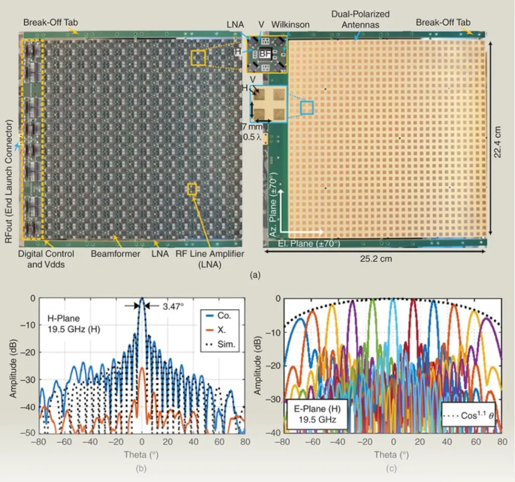
6.2 How Beamforming Works
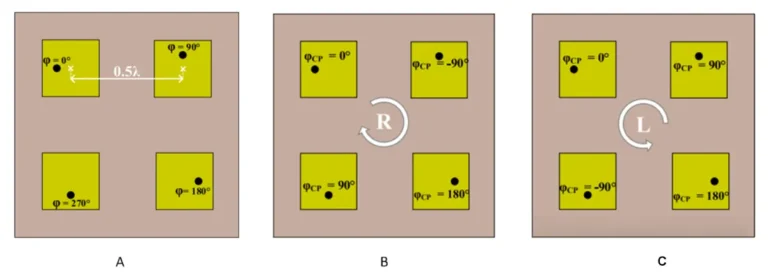
Consider an array containing many radiating elements. When the signals from those elements combine in space, their relative phases determine how strongly they reinforce or cancel one another in different directions.
By adjusting the phase relationships across the array, the system can direct the main beam toward a selected satellite.
The process involves several interacting factors:
Radiating elements: Their geometry and electromagnetic characteristics influence bandwidth, polarization, efficiency, and element radiation patterns.
Element spacing and array geometry: These affect beam steering, mutual coupling, and the possibility of unwanted grating lobes.
RF electronics: Transmit and receive circuitry supports the signal levels, frequency conversion, and phase control required by the system.
Beamforming control: The hardware and software coordinate the array so that the beam can follow the intended direction.
Thermal management: RF and digital electronics generate heat that the enclosure must dissipate while maintaining reliable operation.
The exact implementation can differ between terminal designs. It is therefore important not to assume that every model uses the same number of antenna elements, RF channels, or beamforming architecture.
6.3 Why More Antenna Elements Do Not Automatically Mean Better Performance
The number of radiating elements is only one factor in phased-array performance.
A larger array can provide greater potential gain when its aperture, element patterns, excitation, and losses support that outcome. Yet the relationship between element count and gain depends on the array’s physical dimensions and how the elements are arranged and driven.
Two terminals with different element counts may have different aperture efficiencies, beam patterns, scan performance, and power budgets. Conversely, a reduction in element count does not by itself prove that a product has lost a corresponding amount of practical performance.
Reliable comparisons require more than photographs or inferred element counts. They need verified specifications or measurements that account for antenna gain, scan angle, polarization, transmit power, receiver performance, and other relevant parameters.
This is why claims about the exact internal architecture of a particular Starlink terminal should be supported by reliable technical documentation rather than inferred solely from its external appearance.
7. The Engineering Trade-Offs Behind Terminal Evolution
The development of Starlink hardware illustrates several recurring challenges in antenna and RF product design.
7.1 Size, Weight, and Antenna Aperture
A smaller enclosure can improve portability and make integration into vehicles or other equipment easier. At the same time, antenna aperture remains an important factor in directional gain.
Designers must therefore balance physical dimensions against link requirements, scanning range, and the space available for electronics and thermal management.
Compactness is valuable only when the complete system continues to meet its intended operating requirements.
7.2 Power Consumption and Heat Dissipation
Satellite terminals combine RF transmit and receive circuitry with digital processing, networking, and power conversion. These subsystems all contribute to the overall energy budget.
Reducing power consumption is particularly important for portable equipment and battery-powered platforms. Lower electrical power can also reduce the heat that the enclosure needs to dissipate, although thermal performance depends on where heat is generated and how efficiently it moves through the system.
Power figures should always be compared on a consistent basis. For example, specifications that include the router, power supply, or cables may not be directly comparable with measurements of the antenna unit alone.
7.3 Environmental Protection and Installation
Residential and portable terminals operate outdoors, where they must withstand weather, temperature changes, and mechanical loads appropriate to their intended use.
The antenna enclosure must protect internal electronics without introducing unacceptable RF losses. Mounting structures must also maintain a suitable orientation and resist movement under wind or vibration.
For mobile applications, these requirements become more demanding. Vibration, vehicle movement, limited mounting space, electrical power constraints, and changing satellite visibility all affect the system-level design.
Terminal evolution consequently depends on coordinated improvements across the antenna, enclosure, electronics, software, and mounting system rather than on the radiating elements alone.
8. Beyond Standalone Terminals: Integrating Satellite Antennas into Vehicles
An emerging direction in satellite communication is to integrate antennas into the products that use them.
A conventional vehicle may have several separate antenna assemblies for cellular communication, satellite navigation, Wi-Fi, and Bluetooth. Each system has its own frequency requirements, radiation characteristics, and installation constraints.
Integrating more of these functions into the roof or another suitable vehicle structure could reduce external protrusions and simplify assembly. However, this requires careful attention to RF transparency, antenna placement, electromagnetic compatibility, thermal conditions, and structural safety.
8.1 Why the Roof Material Matters
Metal body panels can block or substantially alter radio-frequency signals. For antennas that need to communicate through the roof, designers may therefore need RF-transparent regions or alternative mounting locations.
Tesla’s published patent application, US20250368267A1, Vehicle Roof Assembly with Integrated RF Transparency for Electronic Module Consolidation, describes a vehicle-roof concept that uses RF-transparent polymer materials and supports the integration of multiple electrical components, including satellite and cellular communication equipment.
The application illustrates a possible approach to combining antennas and other electronics within a vehicle roof assembly. However, a patent describes a proposed design and its claimed embodiments; it does not establish that every illustrated component has entered production or that a particular vehicle uses the configuration.
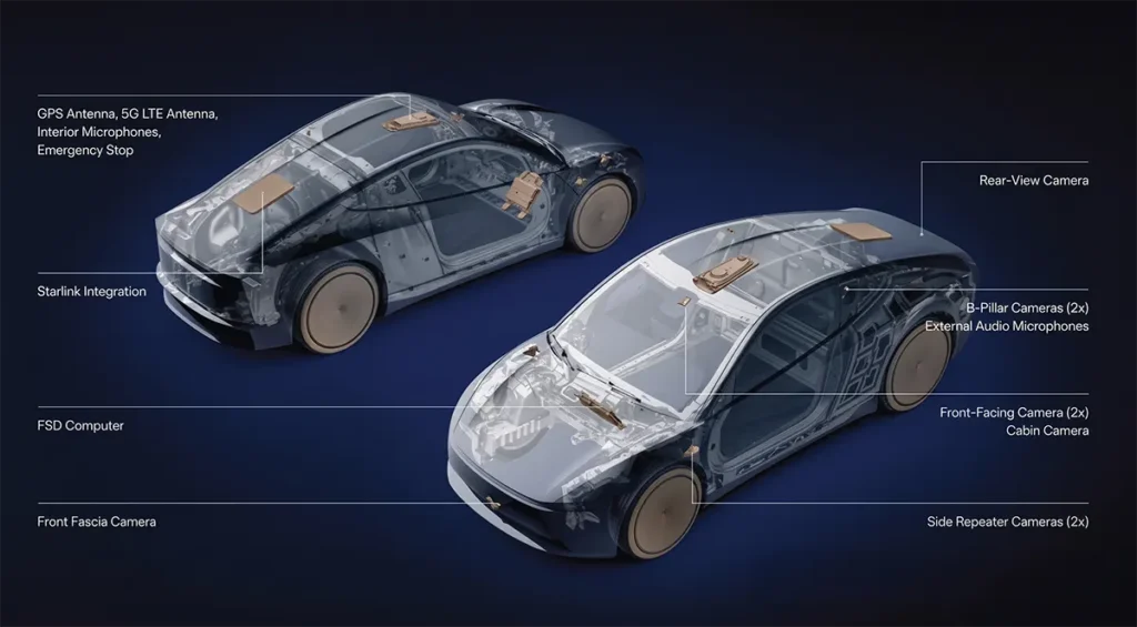
8.2 Integrating Multiple Antennas Requires More Than Saving Space
A vehicle roof may need to accommodate satellite communication, cellular connectivity, GNSS positioning, Wi-Fi, and Bluetooth. These systems operate under different requirements and may interfere with one another if designers do not account for their electromagnetic interactions.
A successful integrated design must consider antenna isolation, radiation patterns, ground structures, material properties, cable routing, and the effects of nearby electronic components. The roof must also meet mechanical, thermal, acoustic, and occupant-safety requirements.
For phased-array satellite terminals, the available sky view and scanning range introduce additional constraints. A low-profile installation must allow the antenna to maintain the required communication link despite the surrounding vehicle structure.
The broader engineering lesson is that integration shifts the design challenge from a standalone antenna toward the performance of the complete product.
9. What the Evolution of Starlink Terminals Tells Us
Starlink terminal development shows how satellite communication hardware can adapt to different applications without relying on a single universal form factor.
Early motorized terminals combined mechanical orientation with electronic beam steering. Later standard hardware reduced dependence on moving parts, while compact products such as Mini prioritized portability and lower power requirements. Other standard and higher-performance models address different installation and operating needs.
Across these product categories, several design principles remain important: adequate antenna aperture, reliable electronic beam steering, efficient RF electronics, manageable power consumption, thermal control, and practical installation.
Future integration into vehicles and other mobile platforms may further reduce the distinction between a standalone terminal and the product that contains it. The extent of this change will depend on verified product designs, application requirements, manufacturing constraints, and network capabilities.
Starlink’s evolution is therefore best understood not as a simple sequence of numbered generations or smaller dishes, but as the continuing development of an integrated satellite communication system in which antenna technology, electronics, software, and mechanical design must work together.
You may also like

Explore RFID deployment challenges as Walmart expands RFID into General Merchandise, including tag placement, RF performance and so on.

UNIQLO RFID Self-Checkout Solution, its “3-step quick checkout” is one of the simplest mobile payment processes. Check and know more details.

Automotive antenna placement for 5G, GNSS, WiFi, BLE, UWB and C-V2X, covering RF design, smart antennas, EMI mitigation and OTA testing.
Discover how Starlink works through LEO satellites, phased array antennas, laser links, and Direct-to-Cell technology.
More Antennas from Airplux Technologies
Optimized for compact RFID devices including handheld readers, desktop readers, and IoT terminals.
Long Range, High Accuracy,Low Profile, Compact Size. Suitabel for Asset Tracking, Inventory Management…
Designed for smart shelves, inventory tracking, smart cabinets, and RFID portal gate systems.
Long Range, High Accuracy,Low Profile, Compact Size. Suitabel for Asset Tracking, Inventory Management…
Engineered for ultra-short read ranges, excellent anti-interference capability.
Long Range, High Accuracy, Low Profile, Compact Size, Industrial Grade, Freezer Compatible.
Contact
We are always ready to serve you.
Please feel free to contact us
for any antenna inquiry or requirement.
Leave us a message in the form below and
we will get back to you within 24 hours.