
How Starlink Works: LEO Satellites, Phased Array Antennas, and Direct-to-Cell
How Starlink Works: LEO Satellites, Phased Array Antennas, and Direct-to-Cell
Introduction
Imagine watching a satellite move across the sky. A traditional satellite dish needs to point in the right direction to communicate with it. But how can a flat Starlink antenna maintain a connection as satellites move overhead—without constantly turning like a conventional dish?
The answer lies in a combination of low Earth orbit (LEO) satellites, electronically steered phased array antennas, and a network designed to move data between space and the ground.
Starlink, developed by SpaceX, uses satellites much closer to Earth than traditional geostationary communications satellites. Its user terminals use electronic beam steering to maintain satellite links, while optical laser links can carry data between satellites. The system also has a different approach for connecting ordinary mobile phones through Direct-to-Cell.
These technologies solve different parts of the same problem: how to deliver useful connectivity when the communication network itself is moving. Understanding how they work together reveals why Starlink is not simply a satellite dish connected to a router, but a coordinated satellite communication system.
1. What Is Starlink and How Does Its LEO Network Work? Why Does Satellite Orbit Matter?
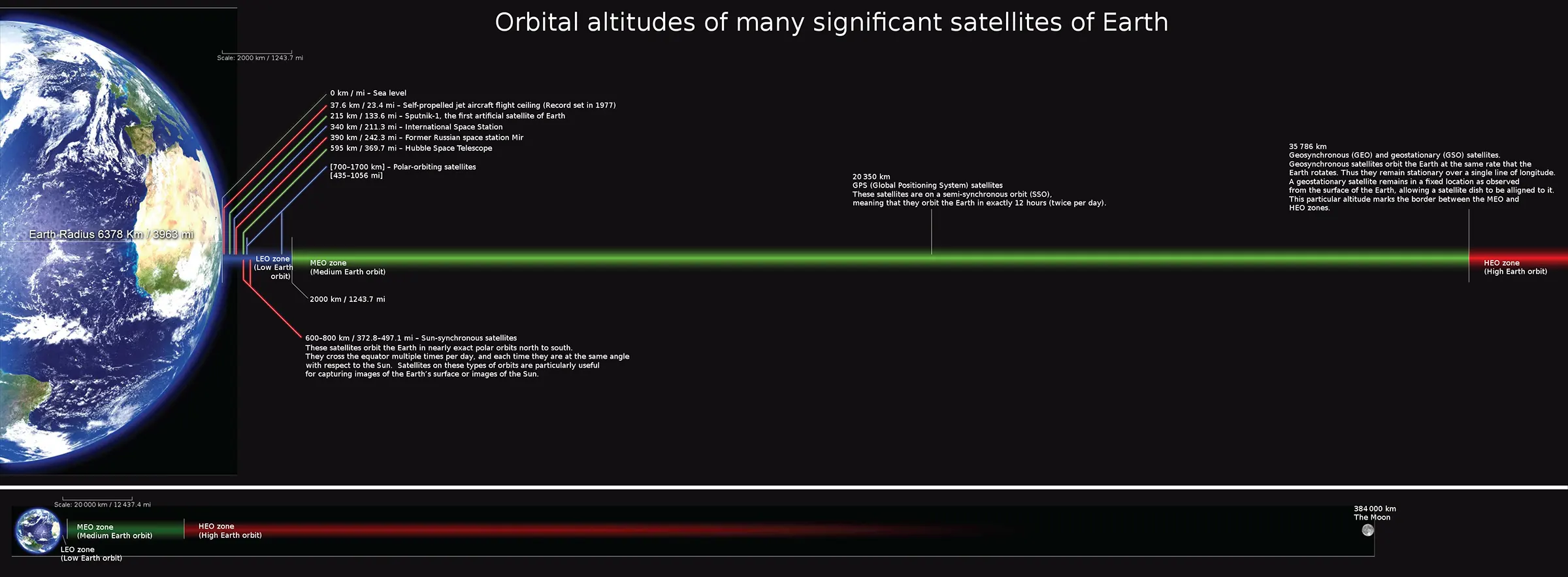
Traditional geostationary satellites orbit approximately 35,786 km above Earth’s equator. Because their orbital period matches Earth’s rotation, they appear almost stationary when viewed from the ground. This makes it practical for a ground antenna to maintain a fixed direction toward a satellite.
Starlink takes a different approach. Its satellites operate in low Earth orbit, at altitudes of hundreds of kilometres. SpaceX uses multiple orbital shells, so there is no single altitude that describes every satellite. Its technology overview uses approximately 550 km as a representative altitude.
The shorter distance can reduce the time signals take to travel between a user and a satellite. Starlink’s public technology material contrasts a representative latency of around 25 milliseconds with the 600 milliseconds or more that can occur in geostationary satellite internet systems. These figures are illustrative rather than guaranteed results for every user; actual latency depends on network routing, congestion, and connection conditions.
There is a trade-off, however. A low Earth orbit satellite moves rapidly relative to a user on the ground. One satellite cannot remain in the same position above a customer indefinitely. The network must therefore manage changing communication links and coordinate connections as satellites move across the sky.
1.1 The Three Main Parts of the Network
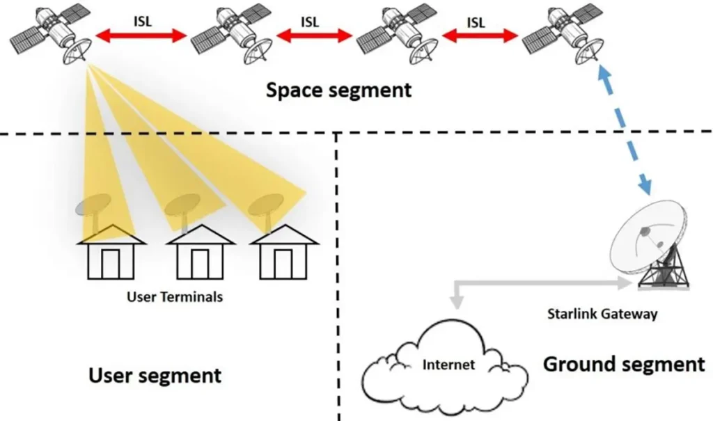
Starlink brings together three main elements: satellites, user terminals, and ground infrastructure.
- Satellites provide communication links between the ground and the constellation. Depending on the satellite design and network configuration, they can communicate with user terminals, ground gateways, and other satellites.
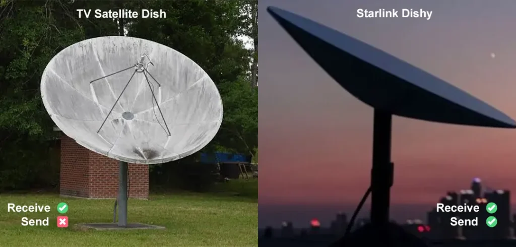
- User terminals connect customers to the satellite network. For residential and business broadband, a terminal typically includes an electronically steered antenna and the equipment needed to establish the satellite connection. A router then distributes the internet connection to local devices.
- Ground infrastructure connects satellite traffic to the wider internet. Gateways, network facilities, and other ground systems provide routes between the satellite network and terrestrial networks.
Direct-to-Cell adds another way to access the system. Rather than requiring a dedicated broadband terminal, it is designed to let compatible mobile phones connect to satellites using spectrum provided by participating mobile network operators.
1.2 What Happens When You Open a Website?
Consider a simple example: you open a website on your laptop using a Starlink connection.
First, the laptop sends a request through your local Wi-Fi network to the router and Starlink terminal. The terminal transmits the data over a radio-frequency (RF) link to a satellite it can communicate with.
From there, the data can travel through an available link to a ground gateway or move between satellites through optical inter-satellite links before reaching suitable ground infrastructure. The network then routes the request to the website. The response returns through an available network path and ultimately reaches your laptop.
This is a simplified example, not a fixed route that every packet follows. The actual path depends on network conditions and the links available at the time.
The important point is that a satellite connection involves more than transmitting a signal into space. The terminal must establish a usable radio link, the network must provide a route for the data, and the system must adapt as satellite positions change.
2. How Do Starlink Satellites Communicate with Earth?
2.1 User Links and Gateway Links
Not every satellite link serves the same purpose.
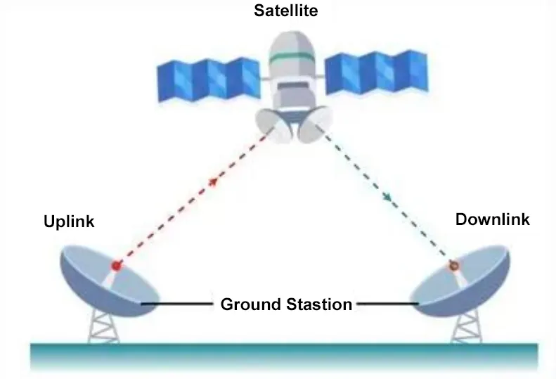
A user link connects a satellite with a customer terminal. A gateway link, also known as a feeder link in satellite communications, connects a satellite with ground infrastructure that links into the wider network.
The distinction matters because these links can use different antennas, frequency allocations, and operating configurations. A frequency authorized for a satellite’s communication with a ground gateway should not automatically be described as a frequency used by a home terminal.
Starlink also uses optical links between satellites in supported configurations. These links provide another route for carrying data through the constellation without using an RF connection for every step.
2.2 Which Frequencies Does Starlink Use?
Satellite communication systems use different frequency bands according to the purpose of each link and the applicable regulatory authorization.
For example, US Federal Communications Commission (FCC) documentation for Starlink’s Gen2 system includes satellite-to-Earth operations in the 10.7–12.7 GHz band and Earth-to-satellite operations in the 14.0–14.5 GHz band, subject to the relevant authorization and conditions. These are examples of Ku-band satellite communication frequencies, not a universal list covering every Starlink satellite and market.
Frequency affects how an antenna is designed, how much bandwidth may be available, and how the radio link behaves. Engineers must consider these factors together with transmit power, antenna gain, receiver performance, and propagation conditions.
Higher frequencies can support wide communication bandwidths, but frequency alone does not determine connection speed or reliability. Those outcomes depend on the complete communication link and the network carrying the traffic.
| Link Type | Frequency Range | Purpose |
|---|---|---|
| User Link (Satellite → User Terminal) | 10.70–12.70 GHz 37.5–42.5 GHz | Satellite transmits data to user terminals |
| User Link (User Terminal → Satellite) | 14.0–14.5 GHz 47.2–50.2 GHz 50.4–51.4 GHz | User terminals transmit data to satellites |
| Gateway Link (Satellite → Ground Station) | 17.8–18.6 GHz 18.8–19.3 GHz 37.5–42.5 GHz | Satellite sends data to ground gateways |
| Gateway Link (Ground Station → Satellite) | 27.5–29.1 GHz 29.5–30 GHz 47.2–50.2 GHz 50.4–51.4 GHz | Ground gateways transmit data to satellites |
| Tracking, Telemetry & Control (Downlink) | 12.15–12.25 GHz 18.55–18.6 GHz 37.5–37.75 GHz | Tracking, positioning, and control (satellite → ground) |
| Tracking, Telemetry & Control (Uplink) | 13.85–14.0 GHz 47.2–47.45 GHz | Tracking, positioning, and control (ground → satellite) |
Note: These frequency ranges are examples based on published regulatory authorizations and Starlink technical materials. Actual frequencies depend on the satellite generation, link type, market, and applicable regulatory approval. This table should not be treated as a universal frequency specification for every Starlink satellite or service.
2.3 Why Link Budget Design Matters
Imagine trying to have a conversation across a large room while someone gradually moves farther away. At some point, the sound becomes too weak to understand. A satellite radio link faces a related engineering problem, although it uses electromagnetic waves rather than sound.
A link budget estimates whether enough signal power will reach the receiver for reliable communication. Engineers account for transmit power, antenna gain, distance-related path loss, receiver characteristics, and other losses along the path.
Antenna performance is one part of this calculation. A directional antenna can concentrate transmitted energy toward a useful direction and improve reception from that direction. But antenna gain alone does not guarantee a reliable link: the transmitter, receiver, propagation path, and operating conditions must all work together.
For Starlink, the challenge becomes more dynamic because the satellite’s position relative to the terminal changes continuously. The system needs to maintain a usable connection while adapting to that changing geometry.
3. Why Does Starlink Use Phased Array Antennas?
3.1 How Can a Flat Antenna Steer Its Beam?
A conventional dish directs energy by using a shaped reflector. To point it toward a different satellite, the dish generally needs to change its physical orientation.
A phased array takes a different approach. It consists of multiple antenna elements whose signals combine to create a directional radiation pattern. By adjusting the relative phase of signals across the array, the system can change the direction of its main beam electronically.
Think of the antenna elements as a group working together rather than as independent radiators. Their signals reinforce one another more strongly in some directions than in others. Changing their relative phase changes how the waves combine, allowing the main beam to be steered.
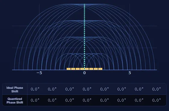
The same broad principle applies during reception: the system combines signals from the array in a way that supports communication from the intended direction.
Starlink identifies phased array antennas as part of its satellite communication technology. This general principle explains how electronic beam steering works, but it does not reveal the proprietary circuit details or exact control algorithms used in a particular Starlink product.
3.1.1 Phase Control and Beam Direction
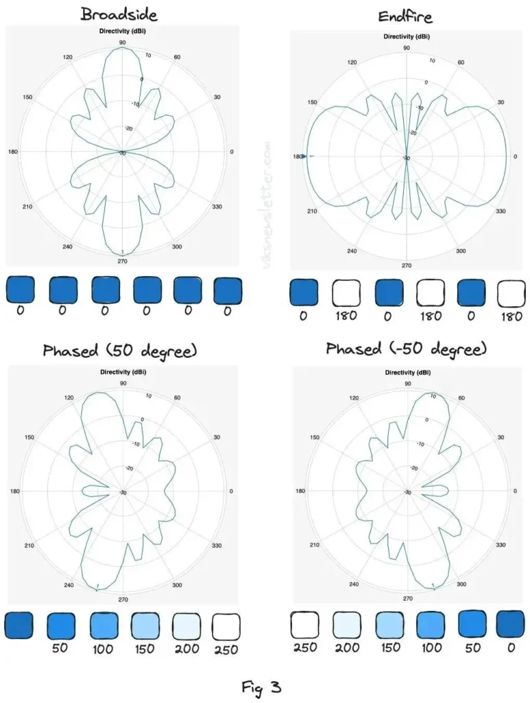
The direction of the main beam depends on the phase relationships between antenna elements, along with the array’s geometry and operating frequency.
In practice, engineers must also consider element spacing, amplitude distribution, scan range, losses, and unwanted radiation in other directions. These factors affect the resulting radiation pattern and the antenna’s performance as the beam moves away from its preferred direction.
These are general phased array design considerations. They help explain the engineering involved without requiring assumptions about Starlink’s unpublished internal circuitry.
3.1.2 Electronic Steering Is Not the Same as Physical Orientation
Electronic beam steering changes the direction of the beam within the antenna’s supported field of view. Physical orientation changes the direction in which the complete terminal faces.
That distinction helps answer the opening question: a phased array can track a satellite electronically without constantly rotating the entire antenna. However, a terminal still needs to be installed and oriented according to its product requirements, and not every Starlink model has the same mechanical design.
For example, the Starlink Standard 4X specification sheet lists a 110° field of view and software-assisted manual orienting. Those specifications describe that particular product rather than every terminal in the Starlink range.
3.2 How Beam Steering Supports a Moving Satellite Network
As a low Earth orbit satellite moves across the sky, the direction of the communication link changes relative to a ground terminal. Electronic steering allows a phased array to adjust its beam within its supported field of view, helping maintain the link.
But beam steering is only one part of the process. Eventually, the current satellite may move away from a suitable position, and another satellite may become a better option. The network must coordinate the transition.
Starlink’s public support material describes automatic switching between satellites as part of maintaining connectivity. The antenna helps establish and maintain a directional link; the wider network manages which satellite and route are available.
This is why Starlink’s operation cannot be explained by antenna technology alone. The antenna, satellite constellation, and network control systems have to work together.
3.3 How Phased Arrays Support Satellite Capacity
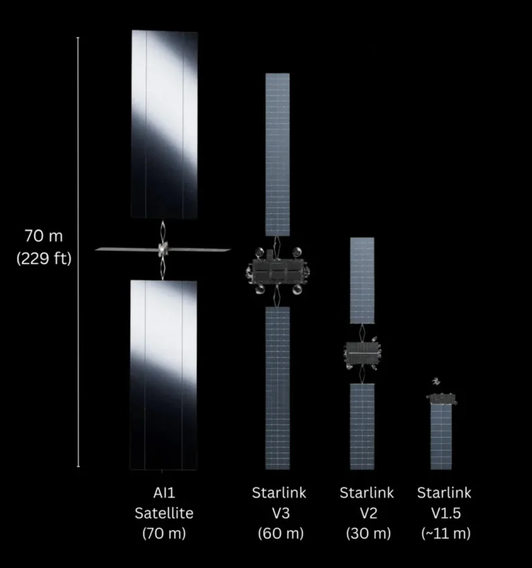
Starlink’s published V3 satellite information illustrates how antenna technology fits into a larger network design.
According to the official V3 overview, the satellite design is intended to support 1 Tbps of downlink capacity and 160 Gbps of uplink capacity, with 2,048 downlink beams and 2,048 uplink beams.
These are published satellite design figures, not the speed a single customer can expect to receive. The satellite serves multiple users, and actual performance depends on how network resources are shared, the user’s connection conditions, and the path taken by data.
The figures nevertheless illustrate an important point: phased arrays are not simply a way to point an antenna at a moving satellite. They are part of the broader design used to manage multiple communication links across a satellite network.
4. Inside the Starlink User Terminal
4.1 The Antenna Is More Than a Flat Panel
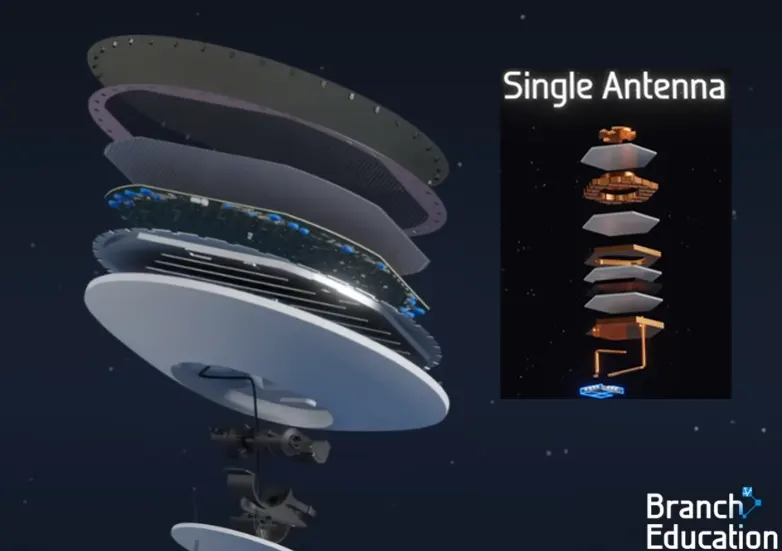
For customers using dedicated Starlink broadband, the terminal provides the RF connection to the satellite network. A flat electronic phased array can steer its beam without requiring the entire antenna to move for every adjustment.
The antenna is only one part of the terminal, however. The system also needs RF electronics, signal processing, control functions, and a connection to the local network. These elements work together to transmit and receive data and maintain the satellite link.
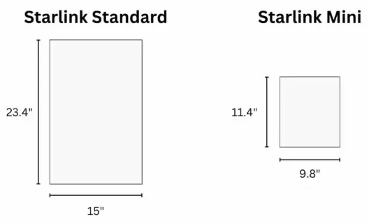
Public product specifications help explain the practical design trade-offs. The Starlink Standard 4X specification sheet lists an antenna measuring approximately 594 × 383 mm, weighing 2.9 kg, with average power consumption of 75–100 W. It also lists a 110° field of view.
Starlink Mini offers a different balance of size and power. Its official specification sheet lists dimensions of approximately 298.5 × 259 mm and average power consumption of 25–40 W.
These examples show how terminal designs can address different installation and portability requirements. They should be read as specifications for the named products, rather than as universal figures for all Starlink hardware.
4.2 What Happens Inside the RF System?
At a general level, the transmit path prepares a radio signal and delivers it to the antenna system, which radiates it toward the satellite. In the receive path, the antenna captures incoming radio energy and the receiving electronics process the signal so that the communication system can recover the transmitted information.
The terminal must coordinate this RF operation with the antenna’s beam direction and the network connection. Its hardware also has to operate within practical limits for power, temperature, size, and environmental exposure.
The exact internal circuitry varies by product and is not fully described in public specification sheets. It is therefore possible to explain the terminal’s role without claiming a specific chip count, circuit layout, or internal signal-processing design that Starlink has not publicly confirmed.
4.3 Why Installation Still Matters
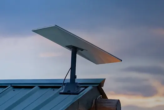
Electronic beam steering does not remove the need for a clear view of the sky. Buildings, trees, roof edges, and other obstacles can block the radio path to a satellite.
Starlink’s installation guidance recommends choosing a location with a clear view of the sky and using the Starlink app’s obstruction-checking feature. The network may switch between satellites when suitable alternatives are available, but obstructions can still interrupt service.
In other words, a capable antenna helps the terminal communicate with moving satellites, but the installation environment remains part of the link. A good location gives the system more opportunities to establish and maintain a usable connection.
5. What Do Starlink's Laser Links Do?
5.1Moving Data Between Satellites
A satellite network does not always need to send data directly to a ground gateway at every step. In supported configurations, Starlink can use optical inter-satellite links, which transmit data between satellites using laser communication.
This differs from the RF link between a satellite and a user terminal. The two technologies serve different roles: radio connects the ground and space portions of the network, while optical links can provide a communication path between satellites.
Starlink’s official technical materials describe laser links as part of its satellite network. Its published specifications vary by satellite design, so a laser configuration or capacity figure for one generation should not be assumed to describe the entire constellation.
5.2 How Laser Links Fit into a Data Route
Return to the example of opening a website. After your terminal sends a request to a satellite, the network needs a path to the website and a route for the response.
Depending on the available links and network configuration, data may travel from satellite to ground infrastructure or pass through other satellites using optical links before reaching a suitable ground connection.
This gives the network another way to move traffic through space. It does not mean every connection follows the same route or that every data transfer can avoid ground infrastructure.

5.3 Why One Link's Capacity Is Not the Whole Story
A published laser-link capacity is not equivalent to the internet speed available to an individual user. A data transfer may cross multiple links and shared network resources before reaching its destination.
Multiplying a link’s stated capacity by the number of links would not, by itself, establish the constellation’s usable end-to-end throughput. That calculation would require information about network topology, traffic allocation, utilization, and other constraints.
The same principle applies to antenna specifications: a capable component contributes to overall performance, but the result depends on how the complete system is designed and operated.
6. Starlink Direct-to-Cell: How Satellites Connect to Ordinary Phones
6.1 How Is Direct-to-Cell Different from Satellite Broadband?
Starlink broadband and Direct-to-Cell solve different connectivity problems.
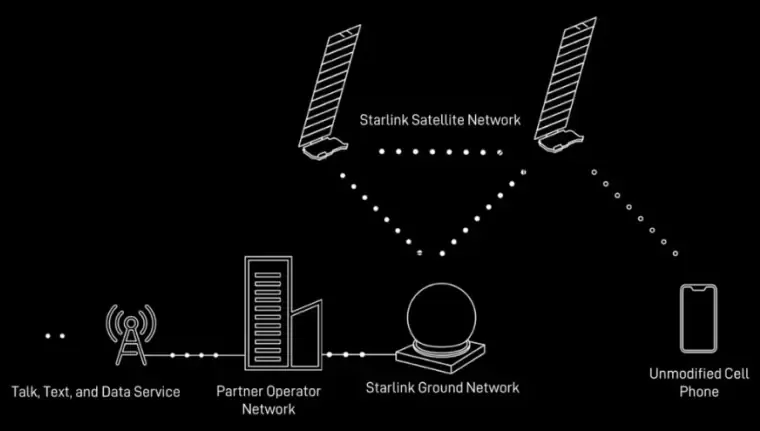
With dedicated satellite broadband, a purpose-built terminal establishes the RF link to the satellite network. Direct-to-Cell is designed to let compatible ordinary LTE mobile phones communicate with satellites without requiring a separate dedicated satellite terminal.
The difference matters because a smartphone is not designed like a dedicated satellite antenna. Its size, antenna gain, transmit power, and battery capacity are constrained by the requirements of a handheld device.
Starlink’s official Direct-to-Cell material describes satellites equipped with phased array antennas, LTE communication equipment, custom silicon, and software algorithms intended to support communication with standard phones.
6.2 How Can a Satellite Act Like a Cell Tower in Space?
In a terrestrial cellular network, a phone communicates with a nearby base station. Direct-to-Cell moves part of that radio access function onto a satellite, allowing the satellite to communicate with phones over a much longer path than a typical ground-based cell link.
The satellite system must work within the capabilities of ordinary mobile devices. The phone cannot simply use the large, specialized antenna system found in a dedicated broadband terminal.
Starlink identifies several challenges associated with this arrangement: mobile phones have limited antenna gain and transmit power, satellites move rapidly relative to users on the ground, and the system must account for Doppler shift and timing constraints.
These conditions require coordination between the satellite’s antenna system, its radio equipment, and the software managing the connection. The general architecture is publicly described, but the complete proprietary physical-layer implementation is not available in public technical material.
6.3 Spectrum and Mobile Network Integration
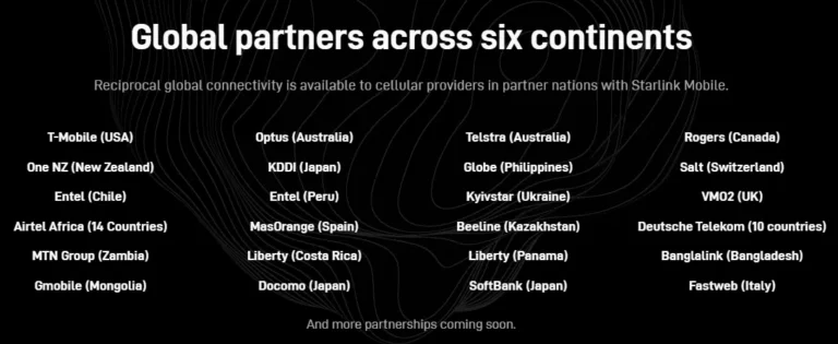
Direct-to-Cell relies on participating mobile network operators, which provide the LTE spectrum used for satellite-to-phone communication.
SpaceX’s published Direct-to-Cell technical update identifies a partner spectrum range of 1.6–2.7 GHz. This is a description of the range used in the stated system context, not a claim that every operator or country uses the same frequency. Actual deployment depends on local spectrum arrangements and regulatory authorization.
The satellite service also needs to connect with the mobile operator’s network. Starlink’s public material describes traffic passing through the Starlink network toward the operator’s core network, allowing the satellite connection to operate as part of the partner’s mobile service.
This integration is a key difference from dedicated satellite broadband. Direct-to-Cell is not simply a smaller version of a Starlink home terminal; it is designed around cellular technology, ordinary phones, and operator networks.
6.4 The Main RF Challenges
- Link budget.
A phone has limited transmit power and antenna gain, but its signal must travel to a satellite hundreds of kilometres away. The satellite-side system must establish a usable link within those constraints.
- Satellite motion.
As the satellite moves relative to the phone, the communication geometry changes. The movement also creates Doppler shift, which changes the apparent frequency of the received signal. The system must account for these effects to maintain communication.
- Timing and handover.
The system must coordinate communication despite the long distance and the changing positions of satellites. It also needs to manage the transition between available satellite links and the operator’s network.
- Shared capacity.
A satellite serves users within its coverage area while distributing available resources across its communication beams. The existence of satellite coverage does not guarantee identical performance for every phone or continuous access to every service.
These challenges explain why Direct-to-Cell requires coordinated RF, antenna, satellite, and cellular-network engineering. No single antenna specification can explain the complete performance of the service.
6.5 What Can Users Expect from Direct-to-Cell?
Starlink’s current Starlink Mobile information describes messaging, data access for supported applications and devices, and app-based voice capabilities. The same page also describes broader capabilities as future service developments.
Because availability changes over time, these descriptions should be checked against the official service page before publication. They should not be presented as a guarantee that every feature is currently available in every country, on every phone, or through every participating operator.
The key idea is that Direct-to-Cell extends mobile connectivity beyond the reach of terrestrial cell sites under supported conditions. It is not a universal replacement for ground-based cellular networks or a direct substitute for dedicated satellite broadband.
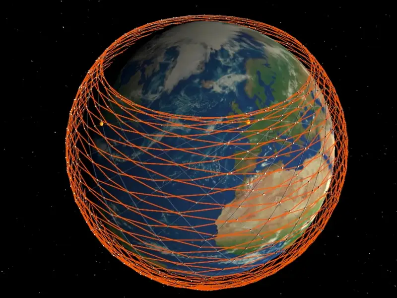
Recent Development: SpaceX Expands Starlink Mobile’s Spectrum
On October 8, 2026, SpaceX announced an agreement to acquire a nationwide portfolio of low-band spectrum licenses in the 800 MHz band from Grain Management, covering up to 14 MHz of paired spectrum. The transaction remains subject to final approval from the U.S. Federal Communications Commission (FCC).
The move highlights an important direction for Starlink Mobile: combining satellite connectivity with terrestrial wireless infrastructure. SpaceX says the additional low-band spectrum is intended to complement its 2 GHz spectrum, helping improve coverage and signal penetration in buildings. Rather than relying on satellites alone, this approach points toward a hybrid network designed to connect mobile devices through both space-based and ground-based infrastructure.
The deal does not, by itself, mean that all indoor coverage challenges have been solved. Its practical impact will depend on regulatory approval, network deployment, and how the satellite and terrestrial systems work together.
7. What Engineering Challenges Affect a LEO Satellite Internet Link?
7.1 Satellite Motion and Handover
A low Earth orbit satellite cannot remain above one customer indefinitely. As it moves, the network must coordinate beam steering and the transition to other available satellites.
A large constellation provides more opportunities for communication, but it also creates a need for effective network coordination. The system must manage the changing availability of links while routing data through the constellation and ground infrastructure.
7.2 Obstructions and Link Availability
A satellite may be above the horizon without providing a clear radio path to a particular terminal. Trees, buildings, terrain, and roof structures can block the connection.
This is why Starlink recommends installing terminals with a clear view of the sky. Satellite switching can help maintain a connection when another suitable satellite is available, but it cannot guarantee that every obstruction will be avoided.
Coverage and link availability are therefore different. Coverage describes where a service may be offered, while link availability also depends on the local installation and current communication conditions.
7.3 Spectrum and Network Capacity
The system also depends on access to suitable radio spectrum, the applicable regulatory permissions, and the capacity available across its communication links.
A satellite’s published beam count or total capacity describes part of the design, not a guaranteed speed for every user. The network must share resources among users and maintain a route through the available links.
Antenna performance, orbital motion, frequency allocation, ground infrastructure, and network management are connected parts of the same engineering problem.
8. What Starlink Shows About Modern Antenna Design
Starlink demonstrates why antenna design is best understood as part of a complete communication system.
A phased array can steer a beam electronically, but the connection also depends on the satellite’s motion, the RF link budget, terminal installation, network routing, and the available spectrum. Optical inter-satellite links provide another way to move data through space, while Direct-to-Cell introduces the additional challenge of communicating with ordinary mobile phones.
The broader lesson applies beyond satellite internet. Antenna performance must match the application, including its operating frequency, radiation pattern, physical size, power limits, environment, and integration requirements.
For engineers developing wireless products, a reliable antenna solution begins with the actual operating conditions and system requirements. Evaluating the antenna alongside the RF hardware and the complete communication link helps ensure that the design supports real-world performance rather than optimizing a single specification in isolation.
You may also like

Learn what Maxwell equations mean, how they unify electricity, magnetism and light, and why they matter in RF and antenna engineering.
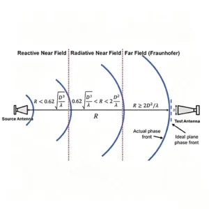
Learn how antenna near field and far field regions work, how to calculate far-field distance, and why antenna size matters.
Explore iPhone antenna evolution from iPhone 1 to iPhone 18 Pro and Duo, covering LTE, 5G, mmWave, Wi-Fi, materials, grounding and RF design.

More Antennas from Airplux Technologies
Optimized for compact RFID devices including handheld readers, desktop readers, and IoT terminals.
Long Range, High Accuracy,Low Profile, Compact Size. Suitabel for Asset Tracking, Inventory Management…
Designed for smart shelves, inventory tracking, smart cabinets, and RFID portal gate systems.
Long Range, High Accuracy,Low Profile, Compact Size. Suitabel for Asset Tracking, Inventory Management…
Engineered for ultra-short read ranges, excellent anti-interference capability.
Long Range, High Accuracy, Low Profile, Compact Size, Industrial Grade, Freezer Compatible.
Contact
We are always ready to serve you.
Please feel free to contact us
for any antenna inquiry or requirement.
Leave us a message in the form below and
we will get back to you within 24 hours.