Automotive Antenna Placement Guide: Optimizing 5G, GNSS, V2X & Vehicle Wireless Performance
Learn best practices for automotive antenna placement, including 5G, GNSS, WiFi, BLE, UWB and C-V2X antenna integration. Explore vehicle wireless system design, RF cable loss, smart antennas, EMI mitigation and full-vehicle OTA testing.
Table of Content
- Introduction
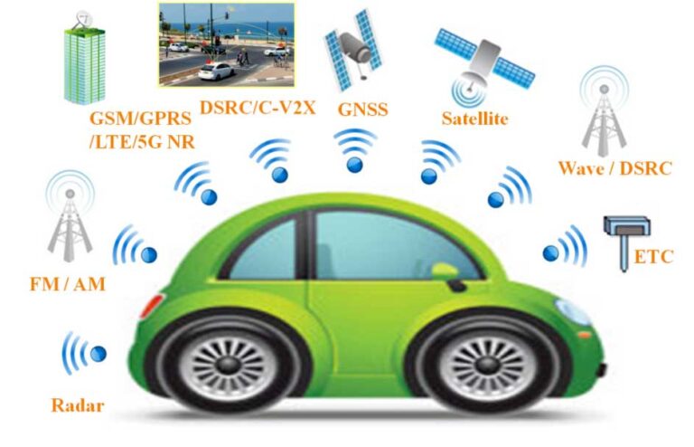
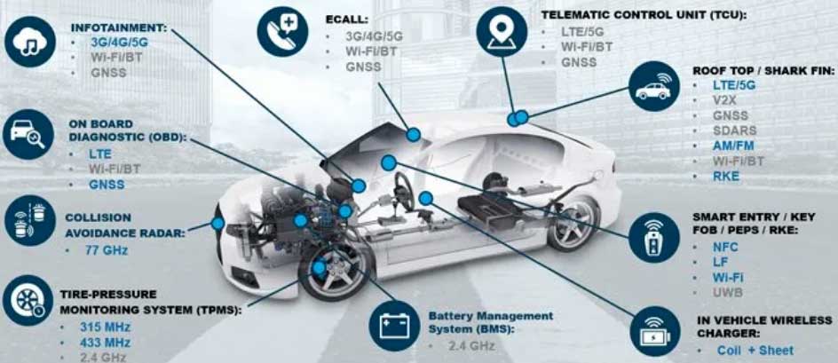
- Wireless Layout: The High-Stakes Game of Vehicle Physics
- Considerations Regarding RF Transmission Cable Loss
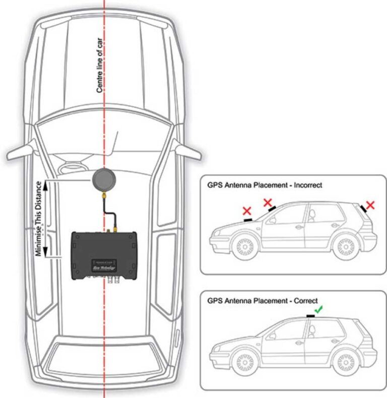
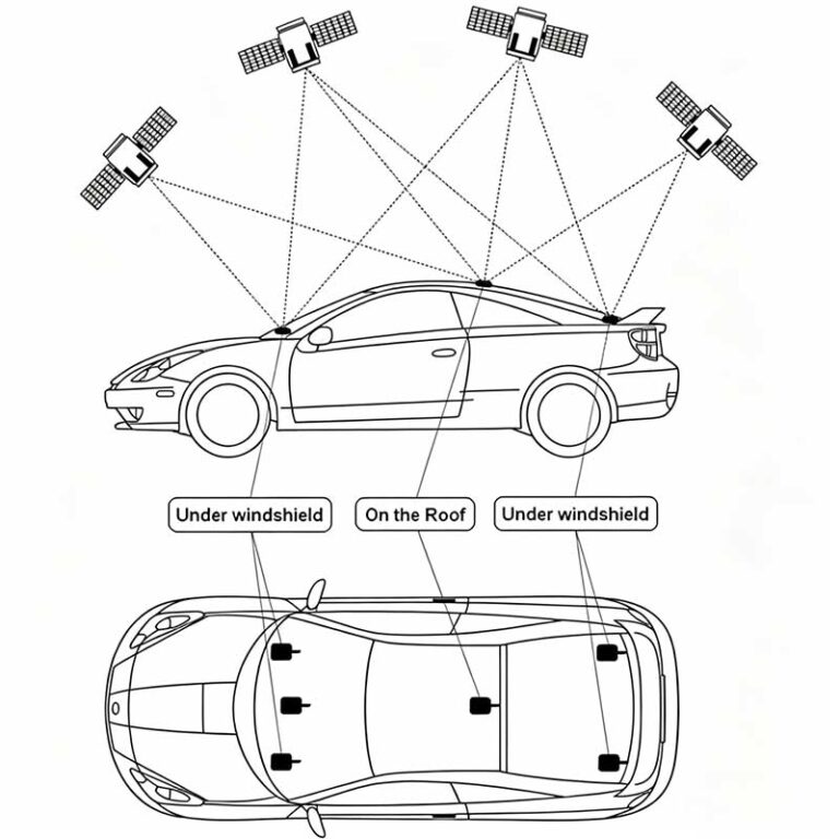
- Guidelines for GNSS Antenna Placement
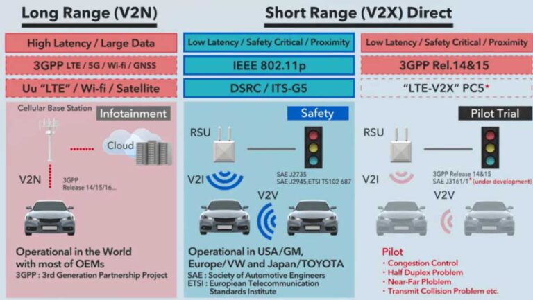
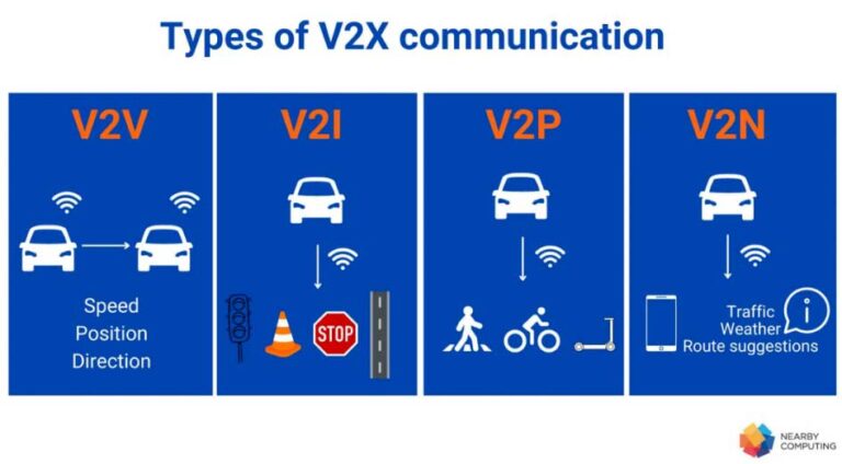
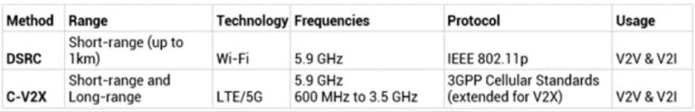
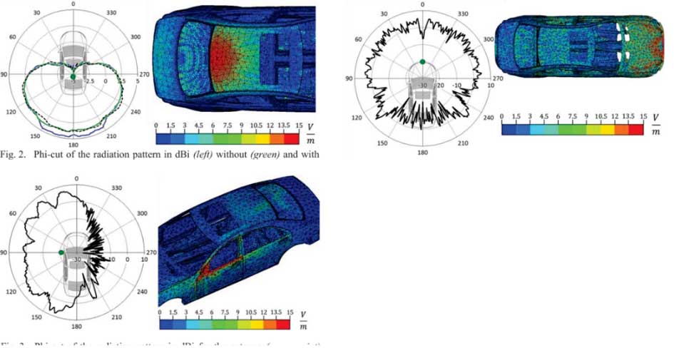
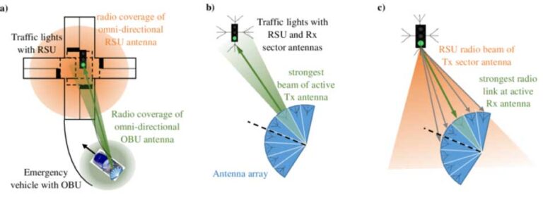
- Guidelines for V2X Antenna Placement
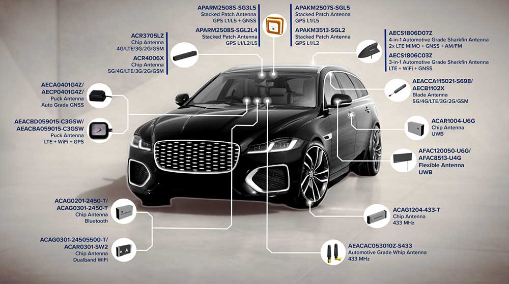
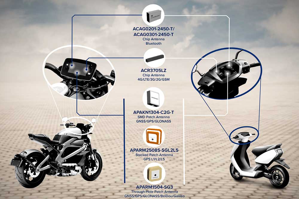
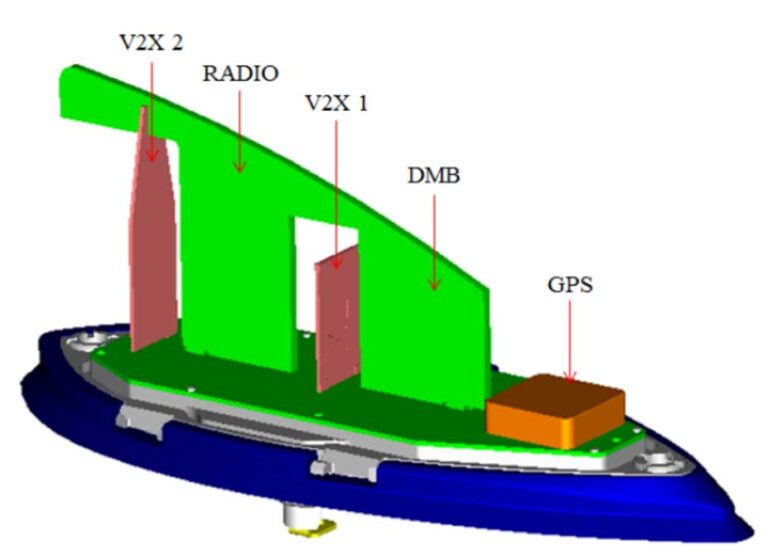
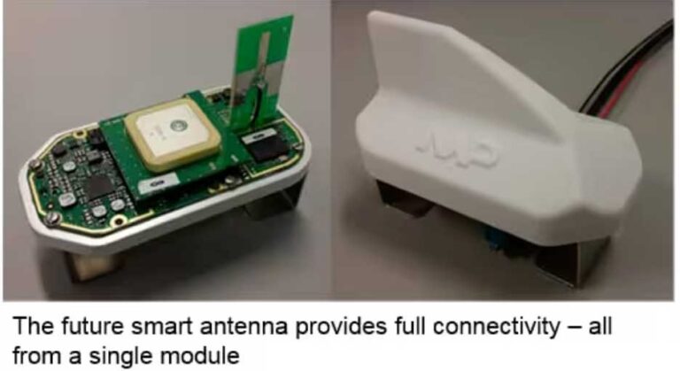
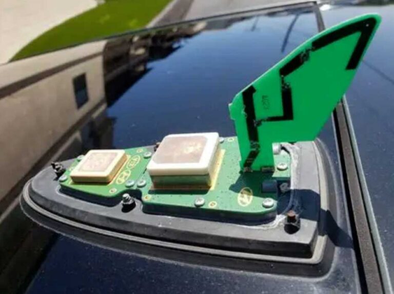
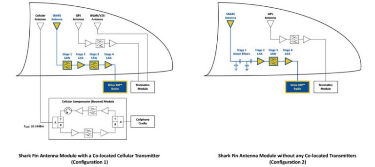
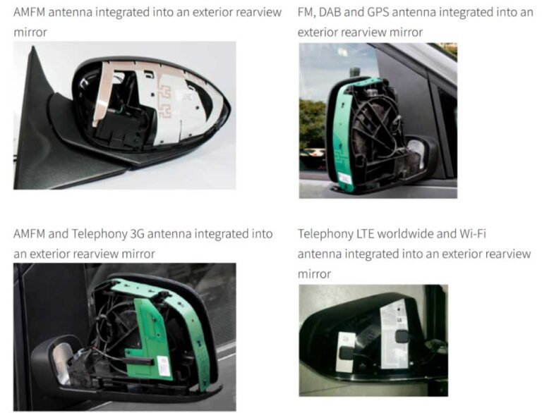
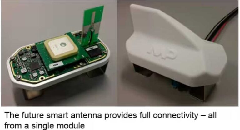
- Case Studies of Multi-Function Integrated Antenna Layouts
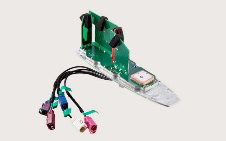
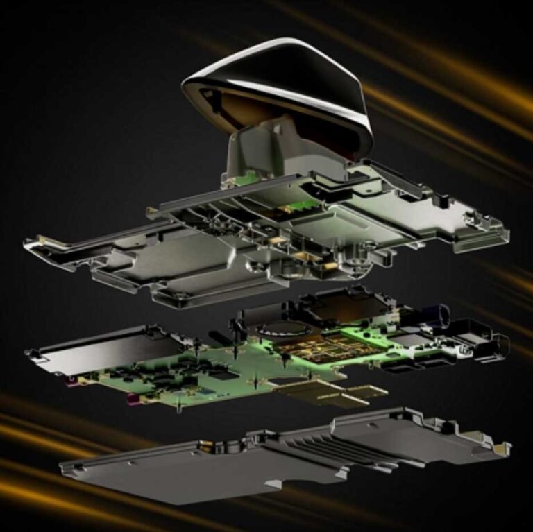
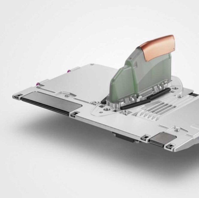
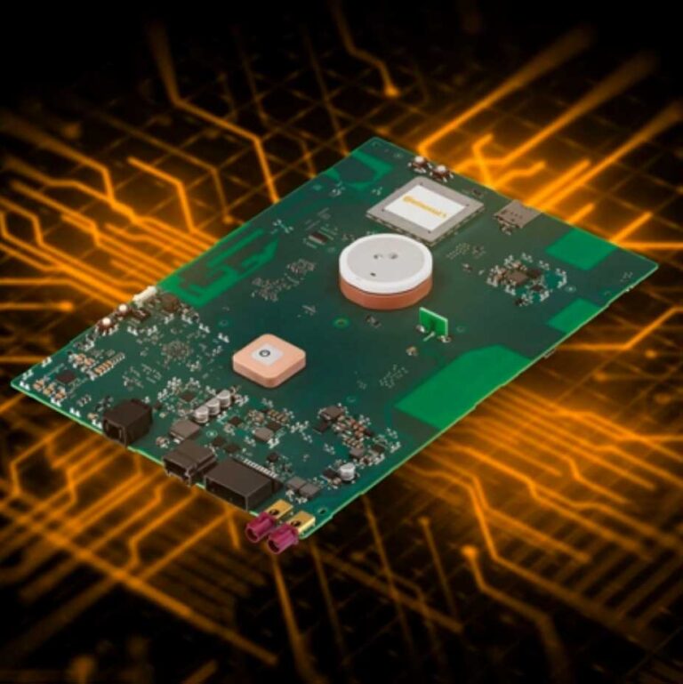
- Case Studies of Antenna + TBox Integrated Module Layouts
- Full-Vehicle Antenna Testing: Validating Performance in a 5G World
- Best Practices for In-Vehicle Wireless Layout: From Theory to Implementation
- Advanced Considerations: Interference, Multi-band, and Vehicle-Specific Layouts