
Electronic Toll Collection: How ETC Systems and Antennas Work
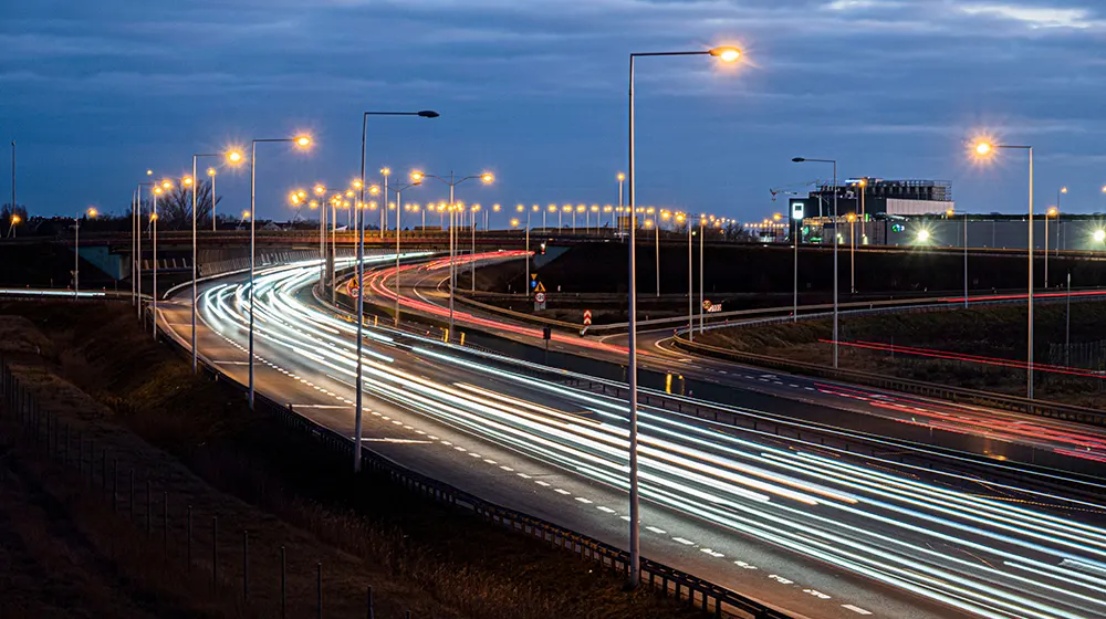
Electronic Toll Collection: How ETC Systems and Antennas Work
- VI. Why Does Vehicle Speed Matter?
- VII. Four ETC Systems That Show How the Technology Has Evolved
- VIII. What the Four Systems Reveal About ETC Technology
- IX. ETC Antenna: Communication Zone vs. Maximum Range
- X. ETC and RFID: Are They the Same?
- XI. Designing an Antenna for Electronic Toll Collection
- Conclusion
Introduction
When a vehicle passes through an electronic tolling point, the transaction can happen without the driver stopping to pay.
The roadside system detects the vehicle, communicates with an in-vehicle device, identifies the vehicle or account, processes the toll, and records the passage. Cameras, vehicle classification equipment, lane controllers, and payment systems may provide additional information.
The basic wireless link is between the On-Board Unit (OBU) in the vehicle and the Roadside Unit (RSU). The antenna connects the RF system to that moving vehicle.
But Electronic Toll Collection is not based on one universal technology. DSRC, passive RFID, automated imaging, and GNSS-based systems are used in different ETC architectures.
To see how these systems work, it helps to start with the transaction itself.
I. How Does Electronic Toll Collection Work?
A typical ETC transaction follows this sequence:
Vehicle detection → wireless communication → vehicle identification → toll processing → transaction record → vehicle passage
When a vehicle enters the relevant detection or communication zone, the roadside equipment identifies the approaching vehicle.
The RSU then communicates with the OBU or tag. Depending on the technology, the exchange may contain a device identifier, vehicle information, transaction data, authentication information, or other protocol-specific messages.
The toll system combines this information with vehicle class, road location, tariff rules, account status, and other required data.
Once the transaction is accepted, the system records the passage. In a conventional toll lane, the lane controller may open a barrier. In a free-flow system, there may be no barrier or stopping point; the vehicle simply continues while the system records the transaction.
RF communication is therefore only one stage of the complete tolling process.
II. OBU, RSU and the RF Link
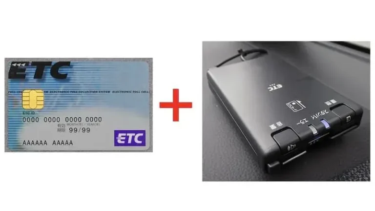
Japanese ETC IC card and On-board equipment
OBU (On-Board Unit) is the vehicle-side device. Depending on the system, it may contain an identifier, security credentials, account-related information, or other application data.
RSU (Roadside Unit) is the infrastructure-side communication device. It is connected to the roadside control system and communicates with vehicles entering its coverage area.
Between the RSU electronics and the vehicle is the antenna.
The antenna converts electrical RF energy into electromagnetic energy for transmission and converts received electromagnetic energy back into an electrical signal.
For a moving vehicle, the communication zone is determined by more than transmitter power. The antenna pattern, mounting position, vehicle speed, OBU position, road geometry, and surrounding structures all affect where communication can take place.
This is why ETC antenna design is closely tied to the physical layout of the tolling point.
III. How Does DSRC Work in ETC?
DSRC (Dedicated Short-Range Communications) is one technology used for ETC communication.
In a DSRC-based system, the roadside unit and the vehicle equipment establish a short-range wireless communication session. The RSU and OBU exchange data according to the applicable communication protocol rather than simply performing a one-way tag read.
Japan is a clear example. Its ETC system uses an active 5.8 GHz DSRC architecture for interactive communication between roadside and vehicle equipment.
The antenna does not determine the toll or interpret the transaction. It provides the RF path through which the communication takes place.
The complete chain is:
RF electronics → antenna → wireless channel → OBU/tag → communication protocol → roadside controller → toll system
Different ETC architectures can replace parts of this chain with different technologies.
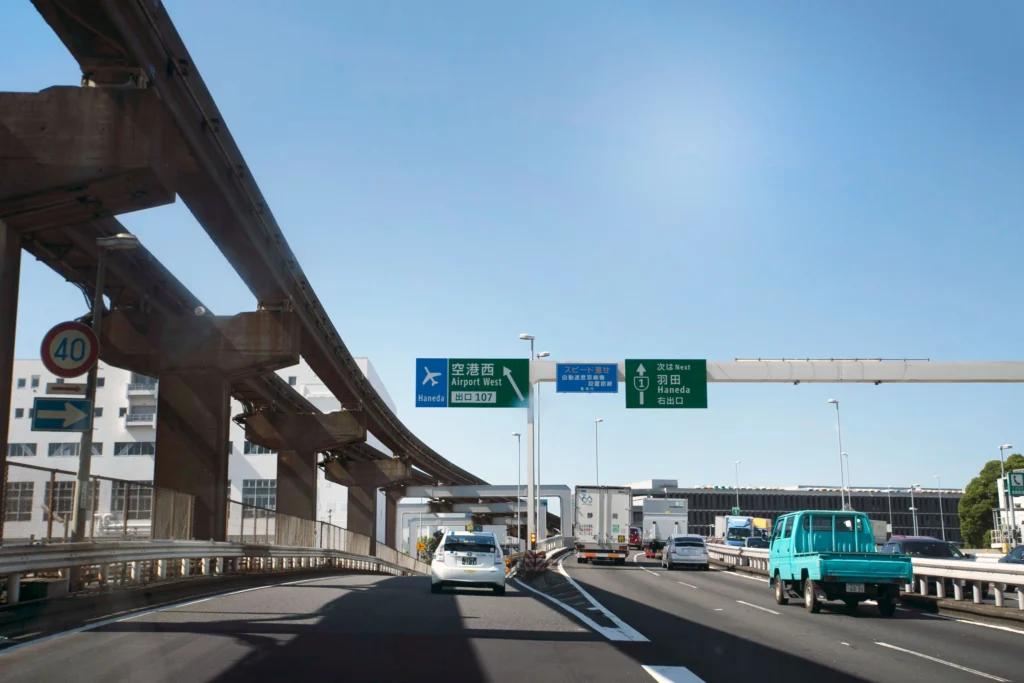
Japanese expressways
IV. What Happens in a Traditional ETC Lane?
A conventional ETC lane can contain several systems working at the same time.
A vehicle detector identifies the vehicle’s arrival. The RSU communicates with the OBU. A camera can capture the license plate or vehicle image. Vehicle classification equipment can determine characteristics relevant to the toll.
The local controller combines these inputs and sends the required information to the toll management system.
If the transaction is valid, the system can activate the traffic signal and open the barrier. Another detector can confirm that the vehicle has passed before the barrier closes.
This architecture gives ETC several ways to identify the same vehicle. An OBU provides electronic identification. A camera provides visual identification. Vehicle classification equipment provides physical characteristics.
These inputs can also be used together when a tag is missing, unreadable, or requires verification.
V. How Does an ETC Antenna Define the Communication Zone?
The antenna does not simply need to provide the longest possible range. It needs to provide a predictable RF field where the ETC transaction can be completed. Several parameters determine that field.
⭐Frequency
The antenna must match the frequency and communication technology used by the ETC system.
There is no single ETC frequency used worldwide.
Japan uses 5.8 GHz active DSRC for ETC, while India’s FASTag uses passive RFID.
The communication standard therefore comes first when selecting an ETC antenna.
⭐Gain
Gain describes how the antenna concentrates RF energy in a particular direction.
Higher gain can increase field strength in the desired direction, but excessive gain can also extend coverage beyond the intended communication area.
The required gain depends on the RSU power, antenna position, communication distance, vehicle path, receiver sensitivity, and coverage target.
⭐Beamwidth and Radiation Pattern
Beamwidth determines how widely the antenna covers the road.
For example, an antenna above a toll lane may need strong coverage along one lane while limiting communication with vehicles in adjacent lanes.
A narrow beam can provide tighter spatial control. A wider beam can cover a larger area.
The correct pattern depends on the road geometry rather than gain alone.
⭐Polarization
Polarization describes the orientation of the electromagnetic field.
The roadside antenna and vehicle-side antenna need a suitable polarization relationship for efficient RF coupling. Vehicle position and OBU installation can change slightly as the vehicle moves through the communication zone.
⭐VSWR and Impedance
The antenna and RF equipment must also be properly matched.
A 50 Ω RF system is common. When the antenna impedance does not match the RF system, part of the transmitted power is reflected toward the transmitter.
VSWR (Voltage Standing Wave Ratio) is one measurement of this mismatch. A lower VSWR generally indicates better impedance matching.
However, a good VSWR value does not guarantee a suitable ETC antenna. The radiation pattern, polarization, gain, and actual coverage zone still need to meet the application requirements.
VI. Why Does Vehicle Speed Matter?
A moving vehicle has limited time inside the communication zone.
For example, if a vehicle travels at 60 km/h, it moves about 16.7 meters per second. If the effective communication zone along its path is 6 meters long, the vehicle remains inside that zone for only about 0.36 seconds.
The communication protocol must therefore complete the required exchange within that available time.
This is different from a fixed RFID application where a reader may repeatedly communicate with a tag while the tag remains in a relatively stable position.
For ETC, vehicle speed, communication time, RF link margin, and antenna coverage have to be considered together.
That difference becomes even clearer when ETC moves from controlled toll lanes to free-flow systems.
VII. Four ETC Systems That Show How the Technology Has Evolved
ETC has developed in different directions depending on the transportation problem each system needs to solve.
Norway, Singapore, Japan, and India provide four useful examples.
Norway AutoPASS: From Toll Lanes to Automated Tolling
Norway’s AutoPASS system shows what happens when physical toll booths are removed from the transaction.
Today, all toll stations in Norway are automated. When a vehicle passes a toll station, the system can generate a transaction from the vehicle’s toll payment tag. If the vehicle has no tag or user agreement, the registration number can instead be captured by image and used for billing.
The technical architecture therefore does not depend on a driver stopping at a payment window.
The vehicle passes through the tolling point while electronic identification and, when necessary, image-based identification provide the evidence needed for the transaction.
This changes the engineering problem.
In a traditional lane, the barrier physically controls where the transaction happens. In automated tolling, the system has to identify the vehicle while it is moving through an open road environment.
The communication zone, camera coverage, vehicle position, and backend processing consequently become part of the tolling architecture.
Evolution:
Controlled toll lane → automated toll station → free-flow vehicle identification
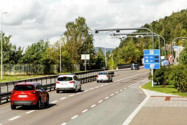
Norway Toll Station
Singapore ERP: From Physical Gantries to GNSS-Based Charging
Singapore’s Electronic Road Pricing (ERP) was introduced to manage road congestion rather than simply collect highway tolls. The existing ERP system has operated since 1998.
The current system uses physical gantries and an in-vehicle unit to charge vehicles when they pass designated charging points.
ERP 2.0 changes the technical architecture.
The new system uses GNSS and an OBU to detect when a vehicle passes an ERP charging location. Physical gantries are being removed from the charging process, with the transition to GNSS-based charging scheduled from 1 January 2027 for Singapore-registered vehicles.
The key change is that the charging location no longer has to be represented by a physical RF gantry.
The vehicle’s location is determined through satellite positioning, and the OBU handles the relevant charging event.
This also changes what “roadside communication” means in the overall system. The charging logic moves from a fixed roadside RF point toward a location-aware vehicle system connected to a broader digital infrastructure.
LTA also states that there are currently no immediate plans to introduce distance-based road pricing.
Evolution:
Physical charging point → gantry-based congestion pricing → GNSS-based road-use charging
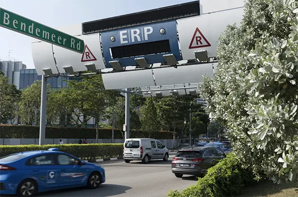
Singapore Toll Station
Japan ETC: From Toll Transactions to Vehicle-to-Infrastructure Communication
Japan demonstrates another direction.
Its ETC system uses 5.8 GHz active DSRC for interactive communication between the vehicle and roadside equipment. The architecture was designed for reliable two-way communication rather than a simple one-way tag reading.
The next step was ETC 2.0.
Japan’s Ministry of Land, Infrastructure, Transport and Tourism describes ETC 2.0 as a 5.8 GHz DSRC system capable of high-speed, high-volume, two-way communication between vehicles and roadside ITS equipment. The service supports applications beyond toll collection, including broader road and traffic information services.
This changes the role of the roadside communication link.
Instead of carrying only the information needed to complete a toll transaction, the same communication infrastructure can support larger data exchanges between vehicles and roadside systems.
The antenna therefore has to operate as part of a communication system designed for more than a single payment event.
Evolution:
Electronic toll transaction → interactive DSRC → high-volume V2I/ITS communication
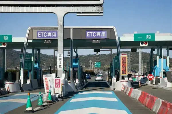
Japan Toll Station
India FASTag: Passive RFID at National Scale
India demonstrates a different approach.
The NETC FASTag system uses a passive RFID tag attached to the vehicle windshield. The tag is associated with the vehicle and a linked payment account, allowing toll payment while the vehicle moves through the toll plaza.
Unlike Japan’s active 5.8 GHz DSRC architecture, FASTag uses a passive tag that responds to the RFID reader’s RF field.
The larger engineering challenge is therefore not only the wireless link but also interoperability.
NPCI’s NETC program provides a nationwide interoperable framework so that a FASTag can be used at toll plazas regardless of which organization operates the plaza.
The scale of the system is substantial. NPCI’s published statistics show more than 127 million FASTags issued by July 2026, with monthly transaction volumes in the hundreds of millions.
This example shows that ETC does not always require a sophisticated active two-way DSRC unit in every vehicle.
A passive RFID architecture can also support large-scale electronic toll collection when the tag, reader, roadside system, transaction platform, and interoperability framework are designed to work together.
Evolution:
Electronic tag → passive RFID tolling → interoperable nationwide deployment

India Toll Station
VIII. What the Four Systems Reveal About ETC Technology
These four systems solve different problems with different architectures.
| System | Communication / Identification | Main Technical Direction |
|---|---|---|
| Norway AutoPASS | Electronic tag + image-based identification | Automated and free-flow tolling |
| Singapore ERP 2.0 | GNSS + vehicle OBU | Gantry-free, location-based charging |
| Japan ETC 2.0 | 5.8 GHz active DSRC | High-volume bidirectional V2I communication |
| India FASTag | Passive RFID | Large-scale interoperable toll collection |
The comparison also explains why there is no single “ETC antenna specification.”
A roadside DSRC system, a passive RFID toll plaza, and a GNSS-based charging system create very different RF requirements.
- In a DSRC system, the antenna helps establish a controlled roadside communication zone.
- In a passive RFID system, the reader antenna has to create an RF field capable of powering and communicating with the tag.
- In a GNSS-based system such as ERP 2.0, the vehicle determines its position through satellite navigation, so the roadside antenna is no longer the mechanism that defines the charging location.
The antenna requirement follows the communication architecture.
IX. ETC Antenna: Communication Zone vs. Maximum Range
For ETC applications, maximum reading distance is not the same as usable communication coverage.
Suppose an antenna can communicate with a vehicle from a long distance. That does not automatically make it suitable for a tolling application.
If the RF field extends too far, the system may detect a vehicle before it reaches the intended toll point or communicate with a vehicle in an adjacent lane.
A useful ETC antenna is therefore designed around the required communication zone.
The design may involve:
- antenna gain
- beamwidth
- radiation pattern
- polarization
- mounting height
- mounting angle
- RF power
- cable loss
- receiver sensitivity
- surrounding
- structures
- vehicle speed
The target is not simply “more range,” but reliable communication within the correct physical area.
X. ETC and RFID: Are They the Same?
ETC and RFID are related, but they are not interchangeable terms.
Electronic Toll Collection describes the complete system used to identify vehicles and process road-use charges.
RFID describes a wireless identification technology that can be used within such a system.
India’s FASTag is a clear example: the overall application is NETC electronic toll collection, while the vehicle-side identification technology is passive RFID.
Other ETC systems use active DSRC or different communication architectures.
So the relationship can be summarized as:
ETC = application/system
RFID, DSRC, GNSS, imaging, and other technologies = possible technologies within the system
XI. Designing an Antenna for Electronic Toll Collection
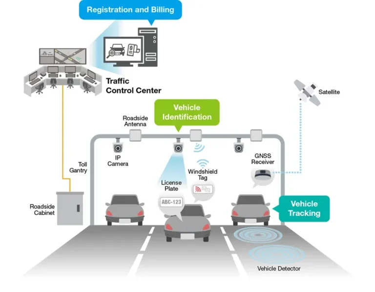
An ETC antenna should be selected from the communication architecture outward.
- First define the communication technology and frequency.
- Then determine the required communication zone from the road layout, vehicle path, speed, mounting position, and lane configuration.
- The antenna’s gain, beamwidth, radiation pattern, polarization, impedance, and VSWR can then be evaluated against that zone.
For systems using RFID or DSRC, the antenna is one part of a larger RF link. Its performance has to match the reader or RSU, vehicle-side device, installation environment, and communication protocol.
That is why an antenna specification sheet alone cannot describe the performance of an ETC installation.
The real question is simpler:
Can the system establish the required communication with the correct vehicle, at the correct location, within the available time?
If the answer is yes, the antenna is doing its job.
Conclusion
Electronic Toll Collection has evolved from controlled toll lanes into several different system architectures.
Norway demonstrates automated and free-flow tolling. Singapore is moving from physical ERP gantries toward GNSS-based charging. Japan has expanded 5.8 GHz DSRC from toll transactions into higher-volume vehicle-to-infrastructure communication. India shows how passive RFID can support interoperable toll collection at national scale.
The underlying principle remains straightforward: identify the vehicle, exchange or obtain the required data, process the charge, and record the passage.
What changes is the technology used to perform those steps.
For ETC systems that rely on wireless roadside communication, antenna design is ultimately about controlling where and when that communication can happen—not simply achieving the longest possible range.
Contact
We are always ready to serve you.
Please feel free to contact us
for any antenna inquiry or requirement.
Leave us a message in the form below and
we will get back to you within 24 hours.