
Antenna Radiation Patterns Explained: A Visual Guide to 85 Antenna Types
Antenna Radiation Patterns Explained: A Visual Guide to 85 Antenna Types
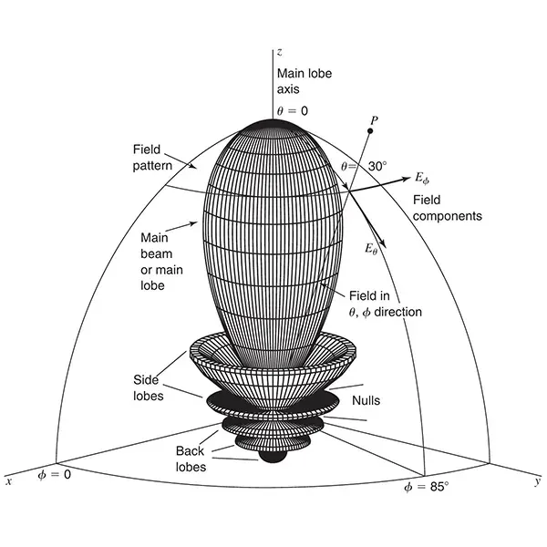
Table of Contents
- What Is an Antenna Radiation Pattern?
- 3D Antenna Radiation Patterns
- Understanding the Main Lobe, Side Lobes and Back Lobe
- From a 3D Radiation Pattern to a 2D Pattern
- Normalized Antenna Radiation Patterns
- Half-Power Beamwidth (HPBW)
- First Null Beamwidth (FNBW)
- Omnidirectional vs. Directional Radiation Patterns
- Why Different Antennas Have Different Radiation Patterns
- 85 Common Antenna Radiation Patterns
What Is an Antenna Radiation Pattern?
An antenna radiation pattern is a graphical representation of how an antenna radiates or receives electromagnetic energy in different directions.
More specifically, it describes the relative field strength or power distribution at a fixed distance from the antenna as a function of direction. Because an antenna radiates in three-dimensional space, its radiation pattern is normally described using the spherical coordinates θ (theta) and φ (phi).
A radiation pattern is also commonly called: Antenna pattern / Antenna beam pattern / Far-field pattern / Antenna directional pattern.
In engineering practice, radiation patterns help us understand an important question:
Where does an antenna radiate most strongly, and where does it radiate weakly?
The answer is often much more useful than simply knowing an antenna’s gain.
For example, two antennas may both have a gain of 8 dBi, but one may concentrate energy into a narrow beam while the other provides much wider coverage. Their radiation patterns can therefore be completely different.
3D Antenna Radiation Patterns
A complete antenna radiation pattern is a three-dimensional representation of radiation distributed around the antenna.
The following example illustrates a directional radiation pattern with its strongest radiation along the Z-axis.
Most of the radiated energy is concentrated in the largest region, known as the main lobe. Smaller radiation regions may also appear around or behind it.
The overall shape of the pattern tells us whether an antenna is: Omnidirectional / Directional / Bidirectional / Highly focused / Wide-beam / Multi-lobed.
This is why looking at the radiation pattern is essential when selecting an antenna. Gain alone cannot tell the complete story.
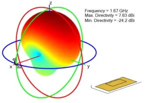
patchMicrostrip
Understanding the Main Lobe, Side Lobes and Back Lobe
Main Lobe
The main lobe is the lobe containing the maximum radiation intensity.
For a directional antenna, it represents the primary direction in which the antenna transmits or receives electromagnetic energy most effectively.
In the pattern above, the strongest radiation is concentrated toward the front of the antenna. This makes directional antennas useful when energy needs to be focused toward a particular area.
Typical examples include: Yagi-Uda antennas / Panel antennas / Horn antennas / Parabolic reflector antennas / LPDA antennas
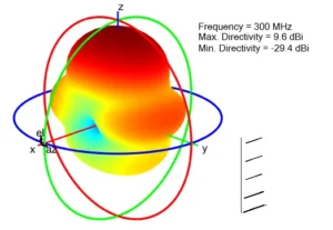
yagiUda
Side Lobes
Smaller lobes outside the main lobe are called side lobes.
The side lobe closest to the main lobe is called the first side lobe.
Side lobes contain less energy than the main lobe, but they are still important. Excessive side lobe radiation can cause unwanted coverage or interference in certain directions.
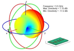
lpda
Back Lobe
Radiation in the direction opposite to the main lobe is called the back lobe.
For many directional antennas, engineers try to reduce rear radiation. One common parameter used to describe this characteristic is the Front-to-Back Ratio (F/B Ratio).
A higher F/B ratio generally means that the antenna radiates much more strongly in the forward direction than toward the rear.
From a 3D Radiation Pattern to a 2D Pattern
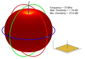
monopole
Although a 3D radiation pattern provides the most complete picture, engineers often examine the antenna pattern in a specific plane. A three-dimensional pattern can be sliced through a selected plane to create a two-dimensional radiation pattern.
The two most commonly referenced planes are E-Plane and H-Plane. The E-plane is the plane containing the electric field vector and the direction of maximum radiation. The H-plane is the plane containing the magnetic field vector and the direction of maximum radiation.
These two views make it easier to measure and compare: Beamwidth, Main beam direction, Side lobe level, Front-to-back ratio and Radiation nulls.
For omnidirectional antennas, the horizontal and vertical patterns may look very different. A vertical monopole, for example, may provide nearly 360° horizontal coverage while having a much narrower vertical radiation pattern.
Normalized Antenna Radiation Patterns
Radiation patterns are commonly normalized so that the maximum radiation value equals 1, or 0 dB. This does not mean every antenna has the same gain. Instead, normalization makes it easier to compare the shape and directional characteristics of different antennas.
For example, if the maximum of a pattern is normalized to 0 dB:
- 0 dB represents the maximum radiation direction.
- -3 dB represents half of the maximum power.
- -10 dB represents much weaker radiation.
- Deep nulls represent directions with extremely low radiation.
This is particularly useful when comparing antennas with different absolute gains.
Half-Power Beamwidth (HPBW)
One of the most important parameters derived from a radiation pattern is the Half-Power Beamwidth, usually abbreviated as HPBW. It is defined as the angular width between the two points on either side of the main beam where the radiated power falls to half of its maximum value.
Half power corresponds to: -3 dB. For this reason, HPBW is also called: 3 dB Beamwidth / -3 dB Beamwidth / Half-Power Beamwidth
A narrow HPBW means the antenna concentrates energy into a smaller angular region. A wide HPBW means the antenna covers a broader area.
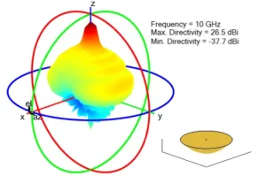
reflectorparabolic
patchmicrostripcircular
For example, compare a highly directional reflector antenna with a wider-beam patch antenna: In general, a narrower beam is associated with higher directivity, although the complete relationship also depends on the overall radiation pattern and antenna efficiency.
First Null Beamwidth (FNBW)
Another important beamwidth parameter is the First Null Beamwidth, or FNBW. It is defined as the angular separation between the first radiation nulls on the two sides of the main lobe.
HPBW and FNBW describe different aspects of the main beam: HPBW describes the width of the beam at the half-power points. FNBW describes the angular width between the first nulls surrounding the main lobe. Both are useful for evaluating directional antennas, especially in applications requiring precise coverage or beam control.
Omnidirectional vs. Directional Radiation Patterns
One of the easiest ways to understand antenna radiation patterns is to compare omnidirectional and directional antennas.
Omnidirectional Patterns
An omnidirectional antenna does not radiate equally in every direction in three-dimensional space. This is an important point.
In antenna engineering, “omnidirectional” usually means the antenna provides approximately uniform coverage around one plane, often the horizontal plane.
A vertical monopole or dipole is a common example.Their three-dimensional patterns are typically similar to a doughnut: strong radiation around the sides and weak radiation toward the antenna axis.
monopolecylindrical
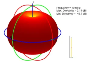
dipolecylindrical
Directional Patterns
Directional antennas concentrate more energy in one or several preferred directions.
These antennas are commonly used where longer range, higher directivity, or controlled coverage is required.
yagiuda
reflectorparabolic
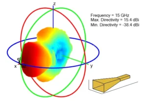
horn
Why Different Antennas Have Different Radiation Patterns
The shape of a radiation pattern is determined by several factors, including Antenna geometry, Physical dimensions, Operating frequency, Polarization, Feeding method, Ground plane or reflector, Nearby structures and Array configuration.
Changing the physical structure of an antenna can significantly change its radiation characteristics. The radiation pattern is therefore closely connected to antenna design.
85 Common Antenna Radiation Patterns
The following radiation patterns cover a wide range of common and specialized antenna structures. The patterns are organized by antenna family to make comparison easier.
1. Biconical, Bowtie and Broadband Antennas
Biconical and bowtie-type antennas are widely known for their broadband characteristics. Their shapes can vary considerably depending on geometry and frequency.
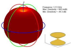
Biconical Antenna
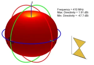
Triangular Bowtie Antenna
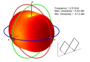
Strip Biconical Antenna
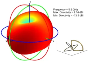
Cloverleaf Antenna
Biquad Antenna
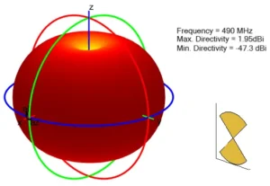
Rounded Bowtie Antenna
2. Dipole Antenna Radiation Patterns
The dipole is one of the most fundamental antenna structures. Different shapes and configurations can modify impedance, size, polarization, bandwidth, and radiation characteristics.
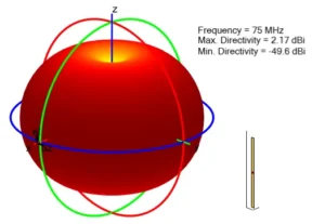
Standard Dipole
Cylindrical Dipole
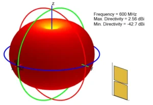
Blade Dipole
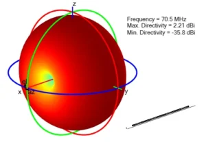
Folded Dipole
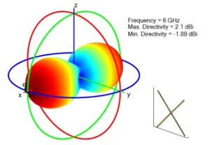
Crossed Dipole
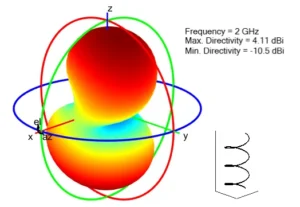
Helical Dipole
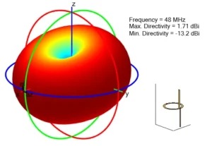
Cycloid Dipole
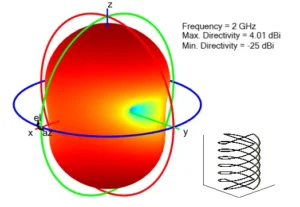
Multifilar Helical Dipole
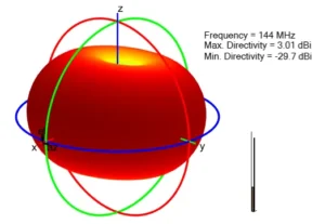
J-Dipole
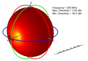
Meander Dipole
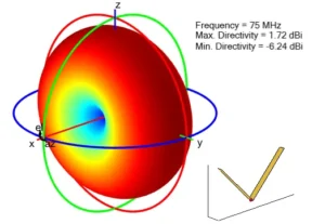
Vee Dipole
3. Monopole and Discone Antenna Radiation Patterns
Monopole antennas are commonly used where wide horizontal coverage is required. Their radiation characteristics can change significantly depending on the ground plane and top-loading structure.
Standard Monopole
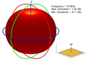
Top-Hat Monopole
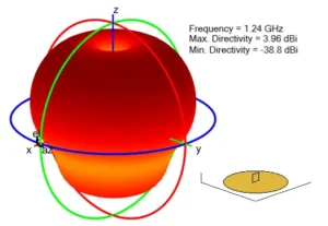
Custom Monopole
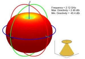
Discone Antenna
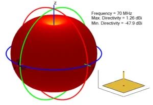
Cylindrical Monopole
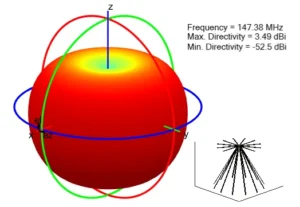
Strip Discone Antenna
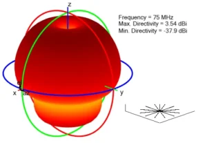
Radial Monopole
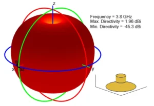
Monocone Antenna
4. Helical and Birdcage Antenna Radiation Patterns
Helical structures can produce different radiation characteristics depending on their dimensions and operating mode.
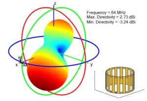
Birdcage Antenna
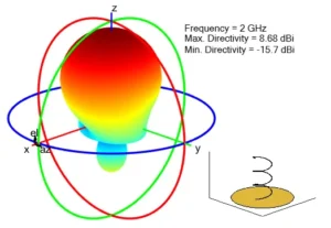
Helix Antenna
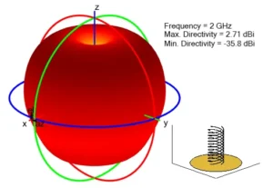
Multifilar Helix
5. Microstrip Patch Antenna Radiation Patterns
Microstrip patch antennas are widely used because of their low profile, compact size, and compatibility with printed circuit boards. They are commonly found in WiFi, RFID, GNSS, cellular, IoT, and embedded wireless devices.
Rectangular Microstrip Patch
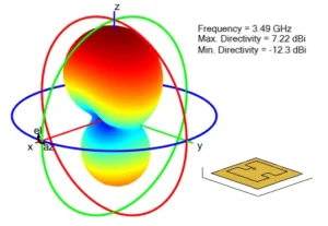
H-Notch PatchTop-Hat Monopole
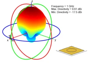
Circular Patch
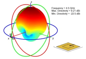
Inset-Fed Patch
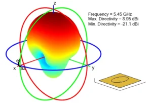
Elliptical Patch
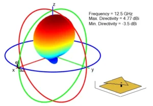
Triangular Patch
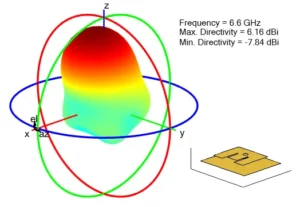
E-Notch Patch
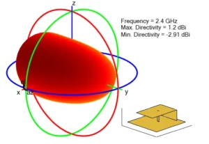
Planar Inverted-F Antenna (PIFA)
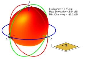
Inverted-F Antenna
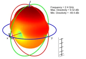
Custom Quad Antenna
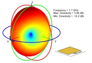
Coplanar Inverted-F Antenna
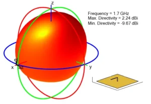
Inverted-L Antenna
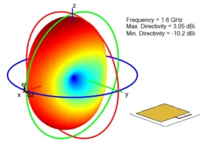
Coplanar Inverted-L Antenna
6. Dielectric Resonator Antenna Radiation Patterns
Dielectric Resonator Antennas, or DRAs, use dielectric materials as the radiating element.
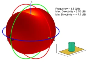
Cylindrical Dielectric Resonator Antenna
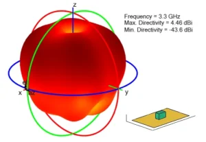
Rectangular Dielectric Resonator Antenna
7. Loop and Slot Antenna Radiation Patterns
Loop and slot antennas use closed conductive paths or slots to generate electromagnetic radiation.
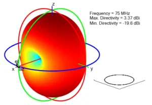
Circular Loop
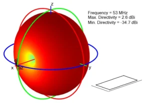
Rectangular Loop
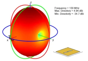
Slot Antenna
8. Fractal Antenna Radiation Patterns
Fractal antennas use repeated or self-similar geometries to achieve compact structures and potentially multi-band or broadband characteristics.
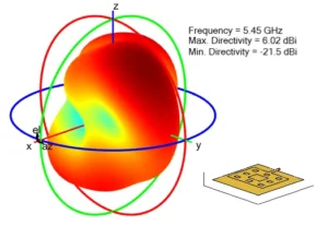
Sierpinski Carpet-Type Fractal
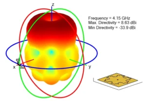
Fractal Snowflake
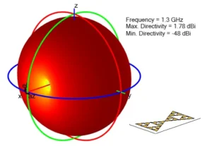
Fractal Gasket
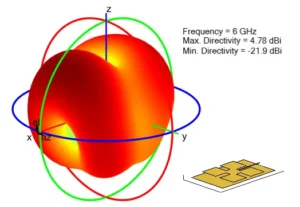
Fractal Island
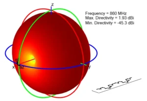
Koch Fractal
9. Spiral Antenna Radiation Patterns
Spiral antennas are often associated with wide bandwidth and, depending on their design, circular polarization.
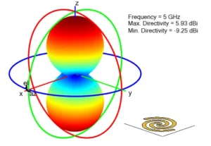
Archimedean Spiral
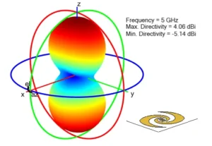
Equiangular Spiral
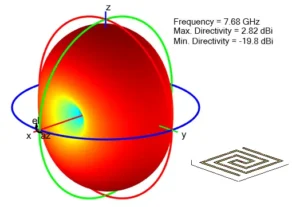
Rectangular Spiral
10. Vivaldi and Tapered Slot Antenna Radiation Patterns
Vivaldi antennas are well known for their ultra-wideband performance and directional radiation.
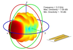
Standard Vivaldi Antenna
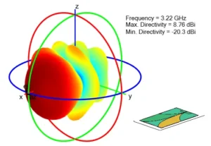
Antipodal Vivaldi
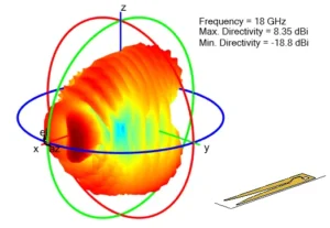
Offset Cavity Vivaldi
11. Log-Periodic and Rhombic Antenna Radiation Patterns
These antennas are commonly associated with broadband directional operation.
Log-Periodic Dipole Array (LPDA)
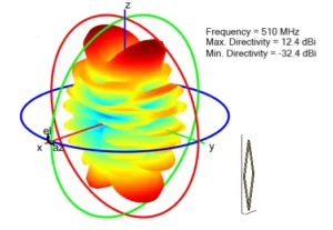
Rhombic Antenna
12. Horn Antenna Radiation Patterns
Horn antennas are directional microwave antennas designed to efficiently transition electromagnetic energy between a waveguide and free space. Their radiation patterns vary depending on aperture shape, corrugation, ridge structures, and other design features.
Standard Horn
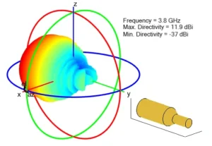
Potter Horn
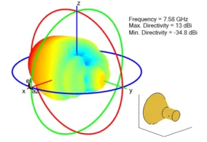
Conical Horn
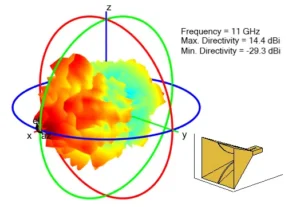
Ridge Horn
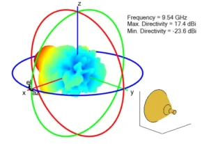
Corrugated Conical Horn
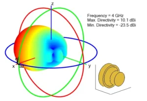
Scrimp Horn
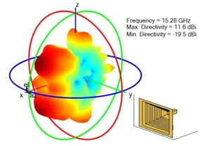
Corrugated Horn
13. Reflector Antenna Radiation Patterns
Reflector antennas use a reflective surface to focus electromagnetic energy. They are widely used in satellite communication, radar, microwave links, and other high-gain applications.
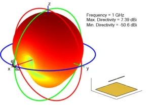
Generic Reflector
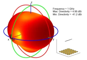
Grid Reflector
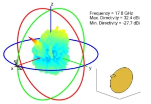
Offset Cassegrain Reflector
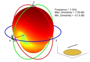
Circular Reflector
Parabolic Reflector
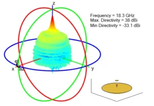
Gregorian Reflector
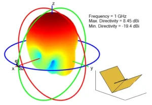
Corner Reflector
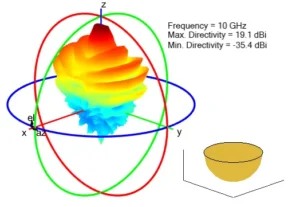
Spherical Reflector
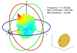
Offset Gregorian Reflector
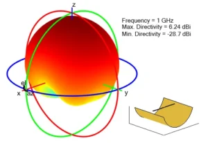
Cylindrical Reflector
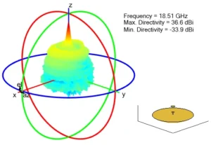
Cassegrain Reflector
14. Cavity Antenna Radiation Patterns
Cavity-backed structures can be used to control radiation and reduce unwanted backward energy.
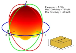
Cavity Antenna
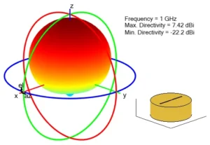
Circular Cavity Antenna
15. Waveguide Antenna Radiation Patterns
Waveguide antennas are widely used at microwave and millimeter-wave frequencies. Their radiation characteristics depend strongly on waveguide geometry, aperture design, and operating mode.
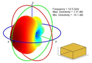
Standard Waveguide Antenna
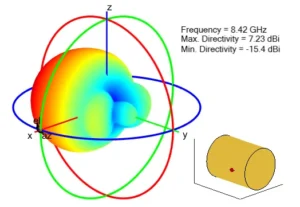
Circular Waveguide
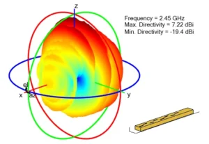
Ridge Waveguide
Slotted Waveguide
16. Sector and Other Specialized Antenna Radiation Patterns
Some antenna structures are designed for specialized directional or sector coverage.
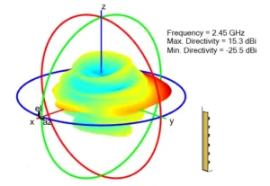
Inverted Amos Sector Antenna
Yagi-Uda Antenna
How to Use Radiation Patterns When Selecting an Antenna
If you need coverage in all horizontal directions, an omnidirectional pattern may be appropriate: Dipole / Monopole / Discone
If you need to focus energy toward one area, a directional antenna may be more suitable: Panel antenna / Yagi-Uda antenna / LPDA / Horn antenna / Reflector antenna
A wide beam covers a larger angular area but generally provides less directional concentration.
A narrow beam concentrates energy more tightly and is useful for long-distance or targeted coverage.
If unwanted signals behind the antenna could create interference, pay attention to the back lobe and front-to-back ratio.
In systems requiring controlled coverage, low side lobes may be important to reduce unwanted radiation outside the intended area.
The final radiation pattern can be affected by Metal surfaces, Ground planes, Enclosures, Mounting structures, Nearby antennas, Walls and other obstacles
The pattern measured in an actual installation may therefore differ from the free-space pattern.
Radiation Pattern vs. Gain: What Is the Difference?
Gain tells you how strongly an antenna can radiate in its maximum direction compared with an isotropic reference antenna. The radiation pattern tells you how that radiation is distributed in different directions.
In simple terms:
Gain tells you how strong the antenna can be. Radiation pattern tells you where that energy goes.
Both parameters are needed to understand antenna performance.
A high-gain antenna is not automatically better. It may simply concentrate energy into a narrower area.For a wide-area coverage application, an antenna with lower gain but a more suitable radiation pattern may provide better real-world performance.
Final Thoughts
Antenna radiation patterns provide a visual way to understand one of the most important characteristics of an antenna: how electromagnetic energy is distributed in space.
By studying the shape of a pattern, engineers can identify the main radiation direction, Main lobe, Side lobes, Back lobe, Radiation nulls, Beamwidth, Coverage area, Directionality.
The 85 antenna radiation patterns shown above demonstrate how dramatically antenna geometry can influence radiation behavior. From the nearly omnidirectional pattern of a monopole to the highly focused beam of a parabolic reflector, every antenna distributes energy differently.
Understanding these differences helps engineers choose the right antenna for applications such as wireless communication, RFID, WiFi, IoT, satellite communication, microwave links, radar, testing, and RF measurement.
Note: All three‑dimensional radiation patterns are reproduced from MathWorks® Antenna Toolbox™ official documentation for built‑in antenna elements. Copyright © The MathWorks, Inc. All rights reserved, used for illustrative purposes only. These are theoretical free‑space simulation results at a fixed reference frequency. Pattern characteristics vary with operating frequency, geometry parameters, ground‑plane and feed configuration.
You may also like

Learn what antenna gain means, how gain relates to directivity and efficiency, how dBi and dBd differ, and how to Choose the Right Gain.

Antenna Array Fundamentals Explained, covering dipoles, antenna elements, array gain, beamforming, and 5G basics.
Learn what is antenna polarization, its types, importance, and applications in modern wireless communication systems.