
UHF RFID Ceramic Antenna – APCA1828

UHF RFID Ceramic Antenna
Model: APCA1828
Frequency Range: 915MHz/866.5MHz
Polarization: Linear
Gain: 2dBi
Product Descriptions
The APCA1828 is a compact ceramic antenna designed for UHF RFID systems operating at 915 MHz and 866.5 MHz. Its 18 × 18 × 4 mm ceramic element and 28 × 28 mm PCB provide a small footprint for integration into space-constrained RFID devices and reader assemblies. With 2 dBi gain and linear polarization, it is suitable for system designs where antenna size and a defined polarization orientation are important considerations. The combination of ceramic and PCB materials, 50 Ω impedance, and SMA or customized connector options gives equipment designers flexibility when integrating the antenna into their products.
Descriptions
- 915MHz/866.5MHz
- 2dBi
- Linear Polarization
- 18*18*4mm
Applications
- Handheld reader
- Desktop reader
- RF Reader
- Internet of Vehicles devices
Product Specifications
Electrical Specifications
Frequency | 915MHz/866.5MHz |
Gain | 2dBi |
Polarization | Linear |
Axial ratio | ≤5dB |
Impedance | 50Ω |
Connector | SMA or customized |
Mechanical Specifications
Ceramic antenna dimensions | 18*18*4mm |
PCB dimensions | 28*28mm |
Antenna material | PCB & Ceramic |
Operating temperature | -20-60℃ |
Antenna Drawing

Applications

RF Reader

Handheld reader

Desktop reader

Internet of Vehicles devices
PRODUCT SUPPORT
FAQ - UHF RFID Ceramic Antenna
A ceramic RFID antenna is an antenna that uses ceramic material as part of its structure or radiating element. It is designed to transmit and receive radio-frequency signals for RFID communication. Depending on its design and operating frequency, it can be used in applications such as access control, asset tracking, and compact RFID devices.
Ceramic RFID antennas can offer a compact structure and stable electrical characteristics when properly designed. Their small form factor makes them suitable for applications with limited installation space. Actual performance depends on the antenna design, operating frequency, installation environment, and RFID system requirements.
Check the available mounting area, antenna placement, connector clearance, and surrounding components before integration. Prototype testing in the final device is recommended to evaluate actual RFID performance.
It may be suitable for short-range identification applications, depending on the RFID reader, tag, installation, and operating environment. The 2 dBi ±1 dB gain specification alone does not determine the actual reading distance.
Linear polarization works best when the antenna polarization is appropriately aligned with the RFID tag antenna. Tag orientation and movement should be considered when designing the reading area.
Yes. An SMA connector or a customized connector option is available. Confirm the connector type and mounting requirements with the supplier before finalizing your device design.
You may also like
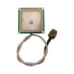
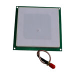
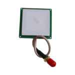
Freq range: 915MHz/866.5MHz
Gain: 3dBi
Polarization: Circular
Dimension: 35*35*4mm
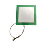
Freq range: 915MHz/866.5MHz
Gain: 5dBi
Polarization: Circular
Dimension: 80*80*6mm
Freq range: 915MHz/866.5MHz
Gain: 5dBi
Polarization: Circular
Dimension: 60*60*5mm
Please feel free to contact us by info@airpluxtec.com for more detailed info if you’re interested in this Antenna, or please check here for our more UHF RFID Ceramic Antenna products.
Contact
We are always ready to serve you.
Please feel free to contact us
for any antenna inquiry or requirement.
Leave us a message in the form below and
we will get back to you within 24 hours.