
5dBi UHF Ultra-thin RFID Antenna
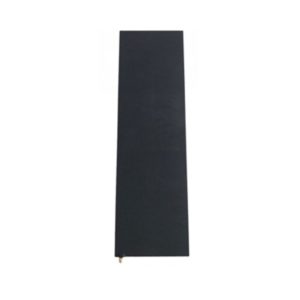
Ultra-thin RFID Antenna
Model: APRIA9005CB
Frequency Range: 902-928MHz
Polarization: Circular
Gain: 5dBi
Product Descriptions
The APRIA9005CB features an ultra-thin PCB design that can be integrated into equipment, fixtures, or furniture where a conventional antenna would take up too much space. Its circular polarization and relatively narrow vertical beam make it suitable for RFID logistics tracking, warehouse applications, access control, and production line management, especially where a low-profile installation is preferred.
Descriptions
- 902-928MHz
- 5dBi
- Circular Polarization
- 440*130*1mm
Applications
- RFID Logistics tracking
- Warehouse applications
- Entrance guard system
- Production line management
Product Specifications
Electrical Specifications
Frequency | 902-928MHz |
Gain | 5dBi |
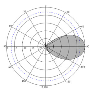
Beam width | Hor:95° Ver:35° |
Polarization | Circular |
VSWR | ≤1.5 |
Impedance | 50Ω |
Maximum power | 100W |
Lightning protection | DC Ground |
Connector | SMA-Female |
Mechanical Specifications
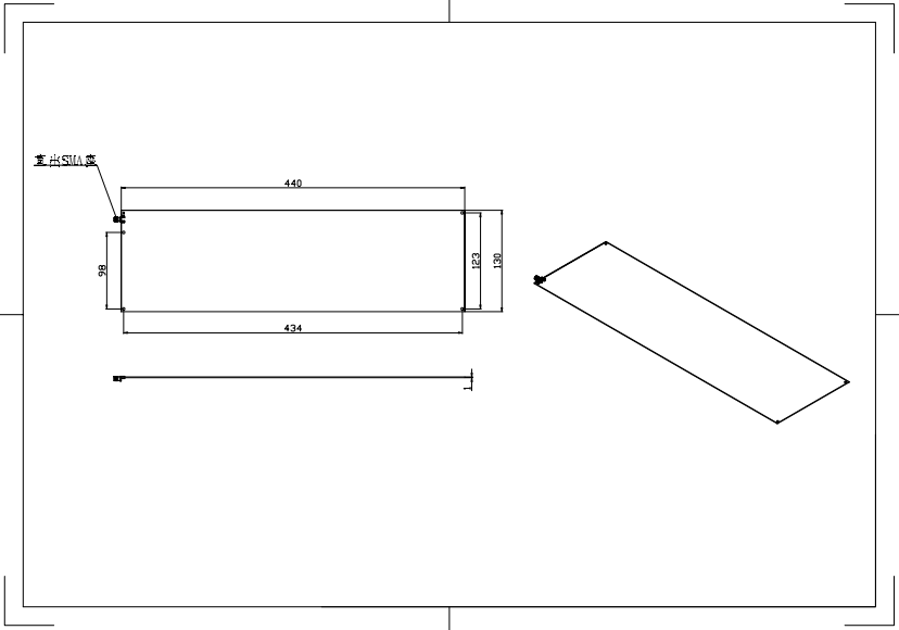
Antenna dimensions | 440*130*1mm |
Net weight | 0.5kg |
Packing size | 49*22*3cm |
Gross weight | 0.8kg |
Radome material | PCB |
Radome color | Black |
Operating temperature | -20-60℃ |
Antenna Pattern
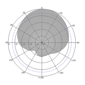
H-Plane
E-Plane
Antenna Drawing
Applications

RFID Logistics Tracking

Warehouse Management

Entrance Guard System

Production Line Management
PRODUCT SUPPORT
FAQ - 902–928MHz UHF RFID Antenna
Choosing the right 902–928MHz RFID antenna involves more than checking its frequency range. Consider the following factors:
- Gain: Determines how RF energy is distributed in the antenna’s radiation pattern.
- Beamwidth: Helps define the intended horizontal and vertical coverage.
- Polarization: Circular polarization can accommodate variations in tag orientation, while linear polarization can work well when tag alignment is predictable.
- Installation: Consider the available mounting space, antenna orientation, and surrounding materials.
- Compatibility: Check the reader’s frequency range, impedance, connector interface, and supported RF power.
The best antenna depends on the reading area, tag placement, and operating requirements of the application.
The 902–928MHz band is shared by different types of wireless devices, so interference may occur when multiple systems operate nearby. In RFID installations, nearby readers and other RF sources may affect reading consistency, particularly in environments with several wireless systems.
Interference management usually involves suitable reader configuration, frequency planning, transmit power control, and frequency-hopping techniques where supported by the system. Antenna selection also matters: an appropriate radiation pattern and polarization can help control the intended reading area. Proper impedance matching supports efficient power transfer, but it does not eliminate interference from other devices.
Ultra-thin RFID antennas can be integrated into equipment, fixtures, workstations, and furniture where installation space is limited. Their low-profile structure allows system designers to incorporate RFID identification into existing equipment layouts without using a conventional bulky antenna housing. They can support applications such as tool identification, work-in-process tracking, and automated inventory checks. The installation position and surrounding materials should be evaluated to ensure reliable RFID communication.
RFID antennas help production lines identify tagged components, work-in-process items, and finished products at designated workstations. As tagged items move through different production stages, the antenna communicates with the tags through an RFID reader, allowing the system to collect identification data and update production records. This supports process tracking, material verification, and production visibility. Antenna placement should be coordinated with product movement and tag position to maintain consistent identification.
When integrating an RFID antenna into furniture or fixtures, consider the available installation space, material thickness, antenna orientation, cable routing, and distance between the antenna and RFID tags. Wood, plastic, glass, and metal can affect RF performance differently, so the installation material should be evaluated before finalizing the design. In particular, metal structures may influence antenna performance and require adjustments to the mounting arrangement. Practical testing is recommended after integration.
Circular polarization provides greater flexibility when RFID tags are attached to items in different orientations. This can be useful in production and inventory environments where products may move through workstations or storage areas in varying positions. Compared with linear polarization, circular polarization is generally less sensitive to tag orientation, although reading performance can still vary with tag placement, distance, and the surrounding RF environment. It does not guarantee reading from every direction.
Please feel free to contact us by info@airpluxtec.com for more detailed info if you’re interested in this Antenna, or please check here for our more RFID Antenna products.
Contact
We are always ready to serve you.
Please feel free to contact us
for any antenna inquiry or requirement.
Leave us a message in the form below and
we will get back to you within 24 hours.