
3dBi UHF RFID PCB Antenna
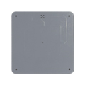
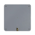
Low Profile 3dBi UHF RFID PCB Antenna
Model: APRIA9003CM-137
Frequency Range: 902-928MHz
Polarization: Circular
Gain: 3dBi
Product Descriptions
The APRIA9003CM-137 is a compact, high-performance 3dBi UHF RFID PCB antenna designed for reliable circular polarization in the 902–928 MHz frequency band. With a slim 137×137×3mm profile and a durable white PCB housing, it delivers a balanced beamwidth (95° horizontal / 65° vertical) and stable VSWR ≤2.0. Ideal for space-constrained environments, this antenna is perfect for RFID logistics tracking, warehouse applications, access control systems, and production line management.
Product Overview
- 902-928MHz
- 3dBi
- Circular Polarization
- 137*137*3mm
Applications
- RFID Logistics Tracking
- Warehouse Applications
- Access Control Systems
- Production Line Management
Product Specifications
Electrical Specifications
Freq Range | 902-928MHz |
Gain | 3dBi |
Beamwidth | Hor:95° Ver:65° |
Polarization | Circular |
VSWR | ≤2.0 |
F/B Ratio | ≥10 |
Impedance | 50Ω |
Max. Power | 50W |
Lightning Protection | DC Ground |
Connector | SMA-Female |
Mechanical Specifications
Dimension | 137*137*3mm |
Net Weight | 0.13kg |
Material | PCB |
Color | White |
Operating temperature | -20-60℃ |
Applications

RFID Logistics Tracking

Warehouse Management

Access Control System

Production Line Management
PRODUCT SUPPORT
FAQ - 902–928MHz UHF RFID Antenna
The 902–928MHz range is a UHF frequency band commonly used by RFID systems in the United States and certain other regions. It is also used by other license-exempt wireless devices, subject to applicable local regulations. Its sub-1GHz operating frequency offers a practical balance between antenna size and radio propagation characteristics, making it suitable for applications such as warehouse inventory, logistics tracking, asset management, and industrial identification.
Airplux offers UHF RFID antennas designed for the 902–928MHz band. When selecting an antenna, make sure its frequency range is compatible with the RFID reader, tags, and regulations in the intended market.
Choosing the right 902–928MHz RFID antenna involves more than checking its frequency range. Consider the following factors:
Gain: Determines how RF energy is distributed in the antenna’s radiation pattern.
Beamwidth: Helps define the intended horizontal and vertical coverage.
Polarization: Circular polarization can accommodate variations in tag orientation, while linear polarization can work well when tag alignment is predictable.
Installation: Consider the available mounting space, antenna orientation, and surrounding materials.
Compatibility: Check the reader’s frequency range, impedance, connector interface, and supported RF power.
The best antenna depends on the reading area, tag placement, and operating requirements of the application.
The Airplux APRIA9003CM-137 UHF RFID antenna measures 137 × 137 × 3mm, making it a compact, low-profile option for installations with limited available space. Its thin PCB structure can be considered for equipment housings, embedded assemblies, and other applications where a slim antenna form factor is preferred. Before installation, check the available mounting area, cable routing, connector clearance, and the required RF coverage.
A 3dBi RFID antenna may be a better choice when the application requires a more localized reading area rather than concentrated RF coverage in a specific direction. Compared with a higher-gain model such as the Airplux APRIA9008CM-206, the APRIA9003CM-137 has lower gain and may offer a wider radiation pattern, depending on the antenna design. The right choice depends on the reading-zone dimensions, tag positions, mounting distance, and the risk of detecting tags outside the intended area.
The Airplux APRIA9003CM-137 specifies a horizontal beamwidth of 73° and a vertical beamwidth of 78°. These values describe the angular width of its main radiation pattern in the two planes. They help engineers assess antenna orientation and plan the intended reading area. Actual RFID coverage and reading distance also depend on reader power, tag characteristics, antenna placement, and reflections from nearby objects.
Voltage Standing Wave Ratio (VSWR) indicates how well an antenna’s input impedance is matched to its RF feed line. A lower VSWR generally indicates better impedance matching and less reflected power at the antenna input. The Airplux APRIA9003CM-137 specifies a VSWR of ≤1.8 across its stated operating band. This specification helps engineers evaluate the antenna’s electrical characteristics, although actual system performance also depends on the reader, cable, connectors, and installation conditions.
Please feel free to contact us by info@airpluxtec.com for more detailed info if you’re interested in this 3dBi UHF RFID PCB Antenna, or please check here for our more WIFI Antenna products.
Contact
We are always ready to serve you.
Please feel free to contact us
for any antenna inquiry or requirement.
Leave us a message in the form below and
we will get back to you within 24 hours.