
12dBi Horizontal RFID Antenna with Enclosure
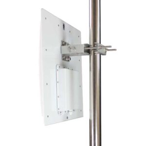
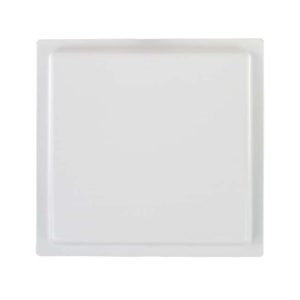
Horizontal RFID Antenna with Enclosure
Model: APRIA80012HD
Frequency Range: 865-868MHz
Polarization: Horizontal
Gain: 12dBi
Descriptions
- 865-868MHz
- 12dBi
- Horizontal Polarization
- 440*440*70mm
Applications
- RFID logistics tracking
- Warehouse management
- Door control system
- Parking lot management
Electrical Specifications | |
Frequency | 865-868MHz |
Gain | 12dBi |
Beam width | Hor:45° Ver:45° |
Polarization | Horizontal |
VSWR | ≤1.3 |
F/B Ratio | ≥25 |
Impedance | 50Ω |
Maximum power | 100W |
Lightning protection | DC Ground |
Connector | Customized |
Mechanical Specifications | |
Dimension | 440*440*70mm |
Net weight | 2.3kg |
Packing size | 60*48*11cm |
Gross weight | 4.25kg |
Radome material | ABS |
Radome colour | White |
Pole Diameter | Φ40-80mm |
Rated wind velocity | 60m/s |
Operating temperature | -40-70℃ |
PRODUCT SUPPORT
FAQ - ETSI UHF Integrated RFID Reader Antenna
An integrated RFID reader antenna is a device that combines an RFID reader and an antenna into a single unit. Unlike a traditional RFID setup that uses a separate reader and external antenna, this design reduces the number of individual components and simplifies system installation. It can be used in applications such as access control, inventory management, asset tracking, and automated identification. The exact functions depend on the reader’s communication interfaces, supported protocols, and system configuration.
An integrated UHF RFID reader antenna sends radio-frequency signals to detect nearby RFID tags. When a compatible passive UHF tag receives the signal, it uses the energy from the reader’s transmission to respond with its stored identification data. The integrated reader processes this response and makes the collected information available to the connected system. Reading performance depends on factors such as antenna characteristics, tag design, reader settings, and the surrounding environment.
A horizontal RFID antenna can be used with different reader brands when their technical requirements are compatible. Check the operating frequency, 50-ohm impedance, connector type, RF cable, and maximum input power before connection. The reader’s output settings should also comply with the antenna’s power rating and local radio regulations. Compatibility should be confirmed from the actual reader and antenna specifications.
Before replacing an RFID antenna, compare its frequency range, polarization, gain, beamwidth, impedance, connector, and mounting dimensions with the existing unit. A replacement with different radiation characteristics may change the reading area even when it uses the same frequency band. After installation, test tag detection and coverage under normal operating conditions to confirm that the existing system still performs as expected.
Missed RFID reads can result from poor tag placement, incompatible polarization, insufficient reader power, cable losses, interference, or unsuitable antenna positioning. Start by checking the tag orientation and antenna alignment, then review reader settings and cable connections. Testing with actual tagged items in the intended environment helps identify the cause more reliably than changing antenna settings without a clear diagnosis.
Pre-deployment testing helps verify that the antenna works properly with the reader, tags, cables, and installation environment. Tests should cover the intended reading area, tag orientations, item movement, and possible interference from nearby equipment or materials. This process can reveal coverage gaps and unwanted reads before the system is used for daily operations.
Please feel free to contact us by info@airpluxtec.com for more detailed info if you’re interested in this Antenna, or please check here for our more UHF Horizontal RFID Antenna with Enclosure products.
Contact
We are always ready to serve you.
Please feel free to contact us
for any antenna inquiry or requirement.
Leave us a message in the form below and
we will get back to you within 24 hours.