
iPhone Antenna Evolution: From iPhone 1 to iPhone Duo
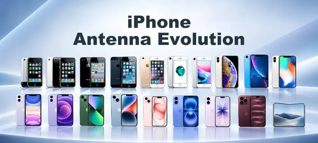
iPhone Antenna Evolution: From iPhone 1 to iPhone Duo
Why Is Smartphone Antenna Design So Difficult?
A smartphone antenna has to work inside an extremely limited space while sharing that space with batteries, displays, cameras, processors, speakers, wireless charging components, sensors, and mechanical structures.
At the same time, modern smartphones must support many wireless technologies simultaneously, including cellular networks, Wi-Fi, Bluetooth, GNSS, NFC, Ultra Wideband, and other short-range or low-power wireless systems.
This makes smartphone antenna design much more than the design of an individual radiating element.
The antenna interacts with:
- the PCB and ground system
- the enclosure and frame
- conductive and dielectric materials
- RF front-end components
- neighboring antennas
- wireless charging systems
- mechanical structures
- the user’s hand and body
- the software and radio system controlling the connection
The evolution of the iPhone provides a useful example of this change.
The story begins with relatively simple internal antennas and eventually reaches a system in which the modem, wireless networking chips, antenna structure, mechanical frame, materials, and device architecture all have to work together.
1. iPhone 1 to 3GS: The Beginning of Internal Smartphone Antennas
The original iPhone, introduced in 2007, used an anodized aluminum rear enclosure and supported GSM/EDGE cellular connectivity together with Wi-Fi, Bluetooth, and GPS. The iPhone 3G introduced in 2008 changed the rear enclosure to plastic, while the iPhone 3GS continued with a plastic rear design.
From an RF engineering perspective, this early period established an important principle: The enclosure is part of the antenna environment.
A conductive enclosure can interact strongly with electromagnetic fields, while a non-conductive material such as plastic can provide more freedom for antenna radiation.
At this stage, the wireless architecture was much simpler than that of a modern smartphone. The design challenge was primarily to integrate the required cellular and short-range wireless antennas into a compact handheld device while maintaining acceptable performance. The antenna was already an internal component, but it was not yet deeply integrated into every aspect of the mechanical structure.
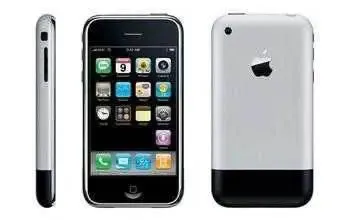
iPhone 1
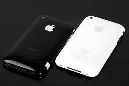
iPhone 3G(black) / iPhone 3GS(white)
2. iPhone 4 and 4S: When the Mechanical Structure Became Part of the Antenna
The iPhone 4, introduced in 2010, represented a major structural change: Its design combined a glass front and back with a stainless-steel external band around the device.
The metal band was not simply decorative. Its segmented structure became closely connected with the phone’s antenna architecture. This was a significant shift in smartphone RF engineering: The mechanical structure itself could become part of the antenna system.
Instead of treating the antenna as an isolated component placed inside a plastic enclosure, engineers had to consider the electrical behavior of the frame, gaps, contacts, grounding points, and surrounding components together.
The iPhone 4S continued this direction while supporting a more complex cellular architecture, including both GSM and CDMA networks as well as expanded positioning capabilities.
As wireless requirements increased, antenna segmentation and RF isolation became increasingly important.
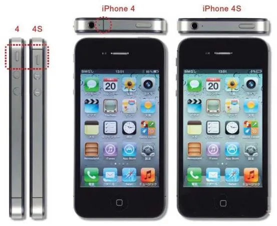
iPhone 4 / iPhone 4S
3. Antenna gate: When User Interaction Became an RF Engineering Problem
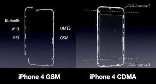
The iPhone 4 became particularly well known for the so-called “Antennagate” controversy. The underlying engineering issue was important because it demonstrated that antenna performance cannot be evaluated independently of the user’s interaction with the device.
Apple stated in July 2010 that holding the iPhone 4 in a particular way could cover the lower-left black strip and cause a significant drop in the number of displayed signal bars. And also acknowledged that its signal-strength calculation formula had been incorrect and could sometimes display more bars than the actual signal conditions justified.
Consequences and Compensation
Apple’s response involved two different issues that should not be confused:
- First, the physical antenna could be affected by the way the phone was held. This is a real RF phenomenon: the user’s hand can alter the electromagnetic environment around an antenna and change its impedance, efficiency, and radiation behavior.
- Second, Apple corrected the software formula used to display signal strength.
That software update improved the accuracy of the signal-bar representation, but Apple explicitly stated that it did not increase the actual signal strength of the device.
From this, we can understand that software can correct the presentation of RF performance, but it cannot automatically restore the physically degraded antenna efficiency caused by human obstruction.
The broader engineering lesson is that RF performance is ultimately a system problem involving the antenna, enclosure, user environment, radio system, and user interface.
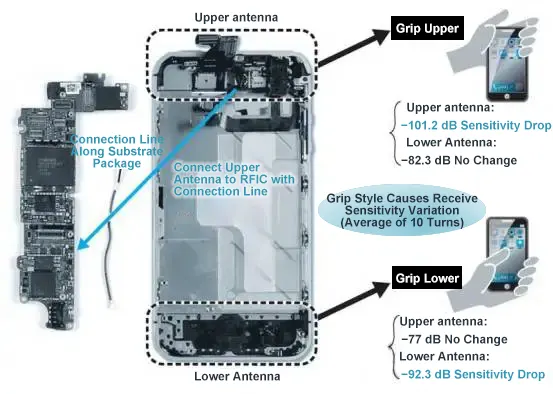
iPhone 4/4S Hand Grip Position and Antenna Sensitivity Variation
4. iPhone 4S: Expanding Wireless Architecture
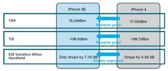
The iPhone 4S further increased the complexity of the wireless system.
Supporting multiple cellular standards and positioning technologies meant that antenna design had to accommodate more operating conditions within essentially the same handheld form factor.
This period marked the beginning of a trend that would become increasingly important:
Every new wireless function competes for physical and electromagnetic space.
The antenna system therefore has to consider:
- frequency separation
- antenna placement
- grounding
- isolation
- matching
- coexistence
- user interaction
These challenges became even more significant as LTE and MIMO entered the smartphone industry.
5. iPhone 5 to iPhone 7: LTE, Metal Bodies and Antenna Segmentation
The iPhone 5 marked the transition into the LTE era.
The aluminum enclosure created a new RF challenge. A large conductive body can influence current distribution and interfere with antenna radiation if the electromagnetic structure is not carefully controlled.
The solution was not simply to abandon metal.
Instead, engineers used controlled antenna segmentation, openings, and carefully defined conductive regions to allow the metal enclosure and antenna system to coexist.
As the iPhone 6, 6s, and 7 generations evolved, the wireless architecture became increasingly sophisticated, supporting broader cellular bands, multiple antenna paths, and MIMO technologies.
This created a new engineering requirement:
The antenna system had to provide multiple independent RF paths without allowing excessive coupling between them.
This is where smartphone antenna design began to move clearly toward multi-antenna and multi-radio system engineering.
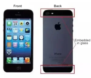
iPhone 5
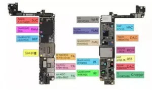
iPhone 7 Logic Board
6. iPhone 8 and iPhone X: Glass, Wireless Charging and Full-Screen Constraints
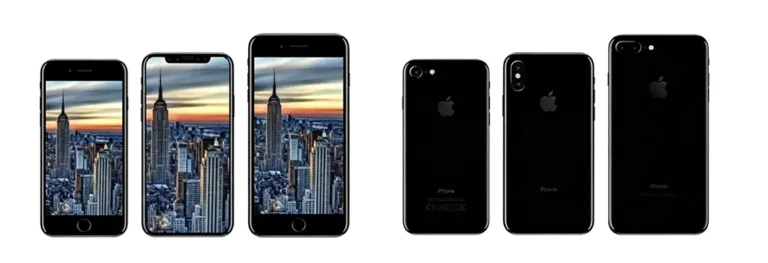
iPhone 8 / iPhone X / iPhone 8 Plus Front and Back Comparison
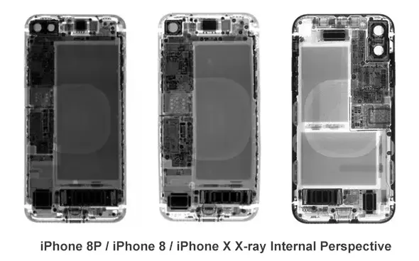
The iPhone 8 returned to a glass rear design, while the iPhone X introduced a new full-screen form factor with a stainless-steel frame.
The glass rear panel provided an important RF advantage compared with a large continuous metal back.
At the same time, wireless charging introduced another electromagnetic system that had to coexist with the antenna architecture.
The phone now had to accommodate:
- cellular antennas
- Wi-Fi and Bluetooth antennas
- GNSS
- wireless charging
- NFC
- a much larger display
- cameras and sensors
The iPhone X also demonstrated another important trend:
Removing unused front space does not remove engineering constraints. It moves them elsewhere.
As displays became larger, the available volume for antennas and other components became increasingly valuable.
7. iPhone XS, XR and iPhone 11: Mature Multi-Radio Integration
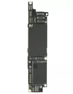
iPhone XR
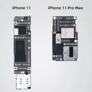
iPhone 11 / iPhone 11 Pro Max
The iPhone XS, XR, and iPhone 11 generations continued the mature multi-radio architecture.
At this stage, smartphone antenna engineering was no longer primarily about making one antenna work.
The challenge was to make many antennas work simultaneously and reliably.
The system had to manage:
- multiple cellular bands
- LTE carrier aggregation
- MIMO
- Wi-Fi
- Bluetooth
- GNSS
- NFC
- wireless charging
- increasingly complex mechanical structures
The design philosophy was therefore moving from individual antenna optimization toward system-level electromagnetic management.
8. iPhone 12 to iPhone 14: From 5G Introduction to a Mature 5G Architecture
iPhone 12: The 5G Breakthrough
The iPhone 12 introduced 5G to the iPhone.
For US models, Apple also introduced support for 5G mmWave.
This was a major change in antenna engineering.
Sub-6 GHz 5G continues to use frequencies that are relatively compatible with conventional smartphone antenna architectures.
mmWave is different.
At much higher frequencies, wavelength becomes much shorter, propagation becomes more sensitive to blockage, and antenna arrays and beamforming become much more important.
The iPhone 12 therefore introduced a more specialized RF architecture in which mmWave antenna modules were integrated into the device structure.
The result was a clear change in design philosophy:
At mmWave frequencies, antenna placement becomes closely connected with beam steering, device orientation, enclosure materials, and user blockage.
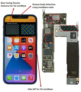
iPhone 12
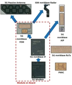
5G mmWave Modular Architecture
iPhone 13: Refinement Rather Than Reinvention
The iPhone 13 generation did not introduce another fundamental change comparable to the arrival of 5G.
Instead, it represented refinement of the 5G architecture.
The engineering focus increasingly shifted toward:
- RF efficiency
- antenna tuning
- coexistence
- power consumption
- coverage consistency
- optimization of a mature multi-band architecture
This is an important part of product evolution.
Not every generation needs a new antenna concept. Many generations improve the existing architecture through incremental RF, mechanical, and system-level optimization.
iPhone 14: Structural and RF Rebalancing
The iPhone 14 generation introduced a significant internal redesign.
Teardown analysis showed extensive grounding-related engineering, including new EMI fingers connecting contact points between the rear panel and internal structure.
This is particularly relevant because modern iPhones have to accommodate cellular 5G, GPS, Wi-Fi, Bluetooth, and satellite-related functions within a highly compact structure.
The lesson is broader than the specific iPhone 14:
Grounding is not simply a PCB detail. In a modern smartphone, the mechanical structure and grounding system can directly influence RF behavior.
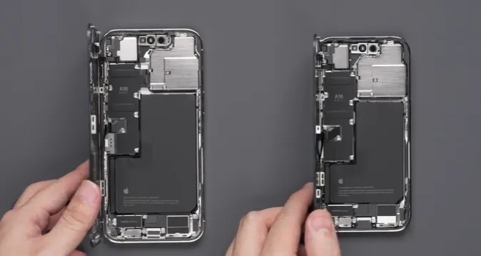
iPhone 14 Pro / iPhone 14
9. iPhone 15: Materials and RF Integration
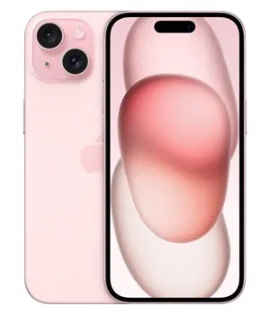
The iPhone 15 generation continued the trend toward highly integrated mechanical and RF design.
The Pro models introduced a titanium enclosure structure, changing the mechanical environment surrounding the internal RF system.
At this stage, the important question was no longer simply:
Where should the antenna be placed?
Instead, engineers increasingly had to ask:
How should the antenna, frame, materials, ground structure, RF front end, and other components work together?
This distinction becomes even more important in the following generations.
iPhone 15
10. iPhone 16: When a New Physical Control Occupied RF Space
The iPhone 16 generation provided a particularly clear example of physical space becoming an RF resource.
The introduction of Camera Control added a new physical interface to the side of the device.
Teardown analysis by iFixit found that one 5G mmWave antenna was removed from the iPhone 16 and iPhone 16 Plus to make room for Camera Control.
iFixit’s examination also found that one mmWave antenna was replaced in the iPhone 16 Pro and Pro Max, while the remaining antenna was moved upward toward the outer edge.
Consequences and Compensation
This should not be described as a case where software simply compensated for the lost antenna.
The publicly available evidence supports a more physical and system-level interpretation.
When antenna space changes, engineers can respond through measures such as:
- antenna repositioning
- aperture and geometry changes
- matching optimization
- RF path optimization
- beamforming strategy
- mechanical and material optimization
However, the public evidence does not establish a specific Apple software algorithm that “compensates” for the removed antenna.
The important engineering lesson is simpler:
Physical controls, cameras, batteries, hinges, speakers, and antennas all compete for the same limited volume.
An industrial design decision can therefore become an RF design problem.
11. iPhone 17: Wireless Integration Becomes the Bigger Story
By the iPhone 17 generation, the wireless architecture had become extremely dense.
Apple’s specifications list:
- 5G
- 5G mmWave on supported models and regions
- 4×4 MIMO cellular connectivity
- Gigabit LTE with 4×4 MIMO
- Wi-Fi 7 with 2×2 MIMO
- Bluetooth 6
- Thread
- second-generation Ultra Wideband
- NFC
- dual-frequency GPS
Apple also introduced the N1 wireless networking chip, which supports Wi-Fi 7, Bluetooth 6, and Thread.
Apple described N1 as improving wireless performance and reliability for functions including Personal Hotspot and AirDrop.
This represents another step in the evolution of smartphone wireless design.
The phone is no longer simply a collection of separate radios.
It is becoming an integrated wireless platform in which: antenna + RF front end + modem + connectivity chip + software + mechanical structure, operate as one system.
12. iPhone 18 Pro: Wireless Architecture Becomes More Integrated
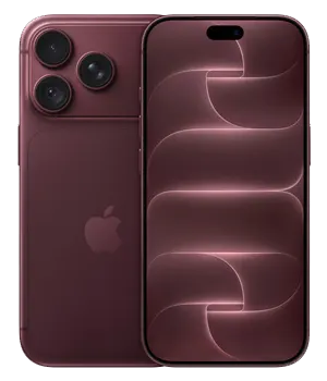
The iPhone 18 Pro generation extends this system-level direction.
Apple introduced the C2 cellular modem system in iPhone 18 Pro and iPhone 18 Pro Max, while the N1 wireless networking chip continues to provide Wi-Fi 7, Bluetooth 6, and Thread.
Apple states that C2 provides AI-powered improvements to cellular quality and reliability, delivers faster uploads compared with C1X, consumes less energy, and supports mmWave in the US.
The official technical specifications also list:
- 5G sub-6
- 5G mmWave
- 4×4 MIMO
- Gigabit LTE with 4×4 MIMO
- Wi-Fi 7 with 2×2 MIMO
- Bluetooth 6
- Thread
- second-generation Ultra Wideband
- NFC
- Apple C2 cellular modem
The significance of this generation is therefore not simply another increase in the number of supported wireless technologies.
The more important development is the increasing integration between the cellular modem, wireless networking subsystem, antenna system, power architecture, and mechanical platform.
iPhone 18
13. iPhone Duo: Folding the Antenna Problem into a New Form Factor
The iPhone Duo introduces a fundamentally different mechanical challenge.
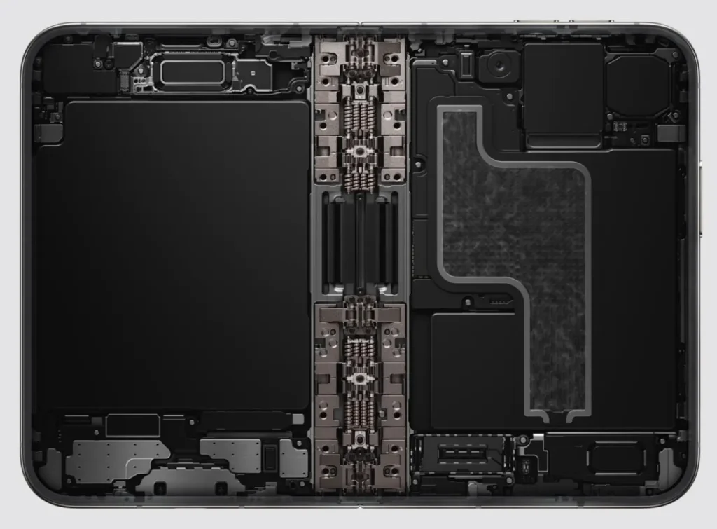
Rather than simply making a conventional smartphone thinner or adding more wireless functions, Apple has introduced a foldable architecture with two sides connected by a precision hinge.
This creates a new RF design question:
How do you maintain a reliable antenna environment when the mechanical structure itself changes configuration?
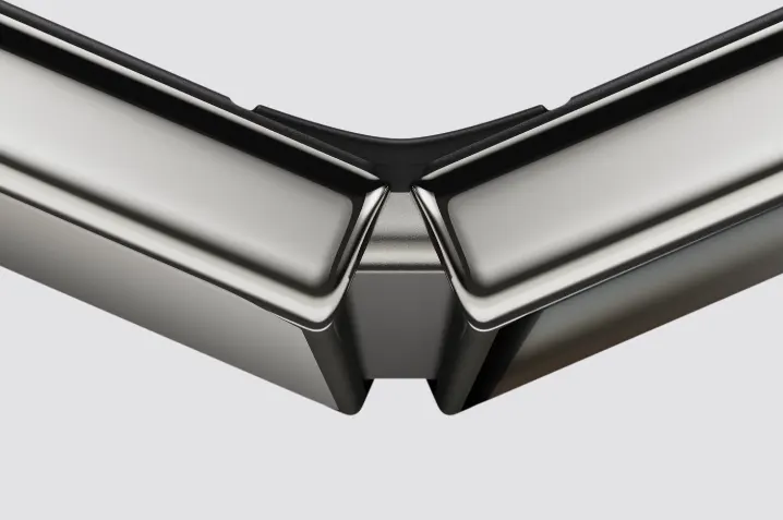
Apple states that iPhone Duo uses a Grade 5 titanium enclosure and a hinge containing more than 100 components.
More importantly for antenna engineering, Apple specifically describes antenna splits with ceramic fiber inserts within the structure.
These inserts serve a structural purpose while the antenna splits also accommodate the mechanical design of the frame.
This is a particularly interesting development in the history of iPhone antenna design.
iPhone Duo
From Antenna Lines to Mechanical RF Architecture
Earlier iPhone generations demonstrated that metal frames could become part of the antenna system.
The iPhone Duo takes this idea into a more complex mechanical environment.
The enclosure must simultaneously provide:
- structural rigidity
- hinge support
- controlled mechanical movement
- electrical isolation where required
- antenna segmentation
- sufficient RF performance
- space for batteries and electronics
The foldable architecture therefore makes mechanical engineering and RF engineering even more closely connected.
This is different from simply adding another antenna.
The physical architecture of the device has become an RF constraint.
iPhone Duo
Wireless Architecture of iPhone Duo
Apple states that iPhone Duo uses:
- C2 cellular modem
- 5G connectivity
- N1 wireless networking chip
- Wi-Fi 7
- Bluetooth 6
- Thread
- eSIM-only architecture
The eSIM-only design is also relevant to the internal engineering story.
Apple says that removing the physical SIM slot saves internal space and helps maximize battery capacity.
That illustrates a broader principle:
Every millimeter of internal volume has multiple possible uses.
The space saved by one component can be reassigned to another requirement, such as battery capacity, structural reinforcement, thermal management, or wireless hardware.
The Duo therefore represents a new stage in smartphone engineering:
The antenna system must coexist not only with electronics, but also with a moving mechanical structure.
At the time of writing, detailed public information about the exact antenna count, individual antenna locations, isolation values, OTA efficiency, and detailed RF compensation strategy remains limited. Those parameters should not be inferred solely from the external design.
For an RF-focused article, it is better to separate confirmed architecture from engineering interpretation.
14. Complete iPhone 1–18 Pro and Duo Evolution Timeline
| Generation | Year | Major Design Direction | Wireless Development | RF / Antenna Significance |
|---|---|---|---|---|
| iPhone | 2007 | Aluminum enclosure | GSM/EDGE, Wi-Fi, Bluetooth, GPS | Beginning of integrated smartphone RF |
| iPhone 3G | 2008 | Plastic rear | 3G | More RF-friendly enclosure |
| iPhone 3GS | 2009 | Plastic rear | Faster 3G | Incremental RF optimization |
| iPhone 4 | 2010 | Glass + stainless steel | GSM/UMTS, Wi-Fi, Bluetooth, GPS | Structural antenna integration |
| iPhone 4S | 2011 | Glass + stainless steel | GSM/CDMA, GPS/GLONASS | More complex RF architecture |
| iPhone 5 | 2012 | Aluminum | LTE era | Multi-band RF with conductive enclosure |
| iPhone 5s | 2013 | Aluminum | Broader LTE / dual-band Wi-Fi | Continued multi-band optimization |
| iPhone 6 | 2014 | Larger aluminum body | Expanded LTE/Wi-Fi | More antenna paths and RF complexity |
| iPhone 6s | 2015 | Refined aluminum | Multi-band cellular | Continued RF optimization |
| iPhone 7 | 2016 | Aluminum | LTE + 802.11ac MIMO | Mature multi-antenna architecture |
| iPhone 8 | 2017 | Glass | LTE + Qi wireless charging | RF and wireless charging coexistence |
| iPhone X | 2017 | Full-screen OLED + stainless steel | Advanced LTE/Wi-Fi | Greater internal space constraints |
| iPhone XS / XS Max | 2018 | Glass + stainless steel | Advanced LTE | Mature multi-radio integration |
| iPhone XR | 2018 | Aluminum + glass | Advanced LTE | RF optimization within different enclosure |
| iPhone 11 | 2019 | Aluminum + glass | Advanced LTE/Wi-Fi | Mature multi-radio platform |
| iPhone 12 | 2020 | Flat-edge design | 5G + US mmWave | Major 5G/mmWave antenna transition |
| iPhone 13 | 2021 | Refined structure | Mature 5G | RF and power optimization |
| iPhone 14 | 2022 | Internal redesign | 5G + satellite-related connectivity | Grounding and structural RF refinement |
| iPhone 15 | 2023 | Aluminum / titanium | Advanced 5G + Wi-Fi | Materials become stronger RF variables |
| iPhone 16 | 2024 | Camera Control | 5G/mmWave architecture | Physical interface competes for RF space |
| iPhone 17 | 2025 | Integrated wireless platform | 5G, Wi-Fi 7, Bluetooth 6, Thread, UWB | Connectivity becomes increasingly system-level |
| iPhone 18 Pro | 2026 | Aluminum unibody | C2, 5G/mmWave, Wi-Fi 7, Bluetooth 6, Thread | Modem, connectivity chip and RF architecture become more integrated |
| iPhone Duo | 2026 | Foldable titanium architecture | C2, 5G, Wi-Fi 7, Bluetooth 6, Thread | Mechanical folding structure becomes an antenna/RF constraint |
15. Six Major Stages of iPhone Antenna Evolution
Stage 1: Internal Antenna Integration
iPhone → 3GS
The primary challenge was fitting cellular and short-range wireless antennas into a compact handheld device.
Stage 2: Structural Antennas
iPhone 4 → 4S
The enclosure and metal frame became closely connected with antenna behavior.
Stage 3: Multi-Band and MIMO RF
iPhone 5 → 7
LTE, broader frequency coverage, and multiple antenna paths increased the importance of isolation, grounding, and multi-antenna coordination.
Stage 4: Multi-Radio Integration
iPhone 8 → 11
Cellular, Wi-Fi, Bluetooth, GNSS, NFC, and wireless charging increasingly had to coexist within a tightly packed architecture.
Stage 5: 5G and System-Level Wireless Architecture
iPhone 12 → 17
5G, mmWave, beamforming, MIMO, Wi-Fi 7, and additional wireless technologies pushed antenna engineering toward system-level optimization.
Stage 6: Integrated Modem and Mechanical RF Architecture
iPhone 18 Pro → iPhone Duo
The latest generation extends the system-level approach in two directions.
The iPhone 18 Pro highlights closer integration between the cellular modem, wireless networking chip, RF system, and device platform.
The iPhone Duo introduces a different challenge: the mechanical structure itself becomes dynamic, making antenna segmentation and structural design part of the RF problem.
16. Engineering Insights and Cross-Industry References
I. Antenna Design Is Increasingly System Design
Modern antenna engineering cannot be separated from the rest of the device.
The antenna interacts with the PCB, ground system, enclosure, materials, RF front end, modem, connectivity chips, mechanical structure and user environment.
This principle applies far beyond smartphones.
It is also relevant to 4G/5G routers, Wi-Fi access points, RFID readers, IoT gateways, automotive wireless systems, industrial wireless equipment and wearable devices.
II. Materials Are RF Design Variables
The evolution from plastic to glass, aluminum, stainless steel, titanium, and specialized inserts demonstrates that materials influence more than mechanical appearance.
Conductive materials can interact strongly with current distribution and electromagnetic fields.
Dielectric materials can affect antenna surroundings and electromagnetic coupling.
In practical antenna design, material selection should therefore be considered together with antenna geometry and placement.
III. More Wireless Functions Increase Coexistence Challenges
A modern smartphone may simultaneously support cellular, Wi-Fi, Bluetooth, GNSS, NFC, UWB, wireless charging, and other wireless functions.
Adding another radio does not simply add another component.
It introduces another electromagnetic interaction.
This increases the importance of:
- antenna isolation
- filtering
- grounding
- matching
- electromagnetic compatibility
- coexistence management
- system-level validation
IV. Physical Space Is an RF Resource
The iPhone 16 provides a clear example of this principle.
When Camera Control occupied physical space previously used by an mmWave antenna, the RF architecture had to adapt.
The iPhone Duo extends this principle even further.
In a foldable device, the available space must also accommodate a hinge, structural reinforcement, two battery sections, displays, and a moving mechanical architecture.
Therefore:
Physical volume is not just a mechanical resource. It is also an RF resource.
V. Higher Frequencies Change the Design Philosophy
The move from conventional cellular frequencies toward 5G mmWave changes the role of the antenna.
At lower frequencies, engineers can often work with compact multi-band antenna structures.
At mmWave frequencies, antenna arrays, beamforming, module placement, blockage, and orientation become increasingly important.
The design problem therefore changes from simply optimizing an antenna element to optimizing an antenna array and its surrounding system.
VI. The User Is Part of the Electromagnetic Environment
Antennagate provided an early and highly visible example.
A user’s hand can change the electromagnetic environment surrounding an antenna.
The same principle remains relevant today, although modern systems have much more sophisticated RF management.
A good antenna design must therefore consider realistic operating conditions rather than laboratory conditions alone.
VII. Mechanical Design and RF Design Are Converging
The progression from the iPhone 4’s metal frame to the iPhone 16’s Camera Control and finally the iPhone Duo’s foldable structure illustrates a broader trend.
Mechanical components increasingly affect RF performance.
For engineers working on wireless products, this means mechanical and RF teams need to consider:
- antenna clearance
- conductive materials
- grounding points
- structural interfaces
- moving parts
- cable routing
- battery placement
- thermal components
- user interaction
early in the design process.
Conclusion
The evolution of iPhone antenna design is not simply a story about adding more antennas. It is the evolution of the relationship between the antenna and the entire device.
- Early iPhone generations focused on integrating antennas into a compact handheld enclosure.
- With the iPhone 4, the mechanical frame became part of the RF system.
- As LTE arrived, broader frequency coverage, multiple antenna paths, and MIMO increased RF complexity.
- From the iPhone 8 through the iPhone 11, more wireless functions had to coexist within an increasingly compact platform.
- The introduction of 5G and mmWave with the iPhone 12 pushed antenna engineering toward arrays, beamforming, and system-level RF optimization.
- By the iPhone 16, even a physical control could create a new antenna-space challenge.
- With the iPhone 17, wireless connectivity continued moving toward a more integrated platform.
- The iPhone 18 Pro takes this integration further through closer coordination between the cellular modem and wireless networking subsystem.
- Meanwhile, iPhone Duo introduces another dimension: the mechanical structure itself can become part of the antenna design problem.
For antenna engineers, the broader lesson is clear:
The future of antenna design is not only about the antenna. It is about how the antenna works with the entire product.
This principle applies equally to smartphones, Wi-Fi equipment, RFID systems, IoT devices, routers, automotive electronics, and industrial wireless products.
You may also like

Explore mobile phone antenna evolution from external whip antennas to invisible structural designs in modern smartphones.

Why do RF systems use 50 ohm impedance? Explore the trade-offs between power handling, transmission loss, coaxial design, and system compatibility.

Learn how to choose the right RF cable and connector. Compare cable types, attenuation, and connector compatibility for better performance.
Contact
We are always ready to serve you.
Please feel free to contact us
for any antenna inquiry or requirement.
Leave us a message in the form below and
we will get back to you within 24 hours.
About Us
Airplux Technologies Limited is one professional Antenna Solution Provider which is integrating R&D, production and sales of antennas. Airplux manufactures superior quality DAS/Small Cell antennas, WiFi antennas, IOT/RFID/M2M/GPS antennas, Base Station antennas and customized antennas from 100MHz to 80GHz. We specializes in the production of custom antennas and related accessories.
Working Hours
- Monday - Friday: 8:00 - 18:00
- Saturday: 8:00 - 12:00
We are always ready to serve you.
Please send email to info@airpluxtec.com,
we will get back to you within 24 hours.