Mobile Phone Antenna Evolution: From Brick Phones to Structural Antennas
Mobile Phone Antenna Evolution: From Brick Phones to Structural Antennas
This article explores mobile phone antenna evolution, tracing how antennas transformed from external whip designs into invisible structural components inside modern smartphones.
Table of Contents
Introduction
The First Mobile Phone Antennas
The Invisible Phone Antenna
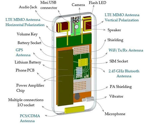
The Smartphone Era: Explosion in Antenna Quantity
Conclusion
Introduction
Today’s smartphones rank among the most highly integrated consumer electronics with the most complex wireless environments in human history. A single phone often needs to support multiple wireless systems simultaneously—including cellular communications, Wi-Fi, Bluetooth, GNSS, and NFC. With cellular communication alone spanning over 60 frequency bands across 2G, 3G, 4G, and 5G.
Accommodating high-performance SoCs, complex RF front-ends, imaging systems, batteries, and structural components within such limited space presents an exceptionally demanding engineering challenge.
While chips can be continuously miniaturized and highly integrated into ICs, antennas—as devices fundamentally constrained by electromagnetic wavelengths—cannot be “shrunk into silicon” like transistors.
This transformation represents a critical chapter in mobile phone antenna evolution, where antenna design gradually shifted from visible external hardware to invisible structural engineering.
So how did mobile phone antennas gradually “disappear” and ultimately become part of the phone’s structure?
The First Mobile Phone Antennas
Today’s smartphones rank among the most highly integrated consumer electronics with the most complex wireless environments in human history. A single phone often needs to support multiple wireless systems simultaneously—including cellular communications, Wi-Fi, Bluetooth, GNSS, and NFC. With cellular communication alone spanning over 60 frequency bands across 2G, 3G, 4G, and 5G. These early designs laid the technical foundation for mobile phone antenna evolution, defining how size, radiation patterns, and grounding would shape future handset antennas.
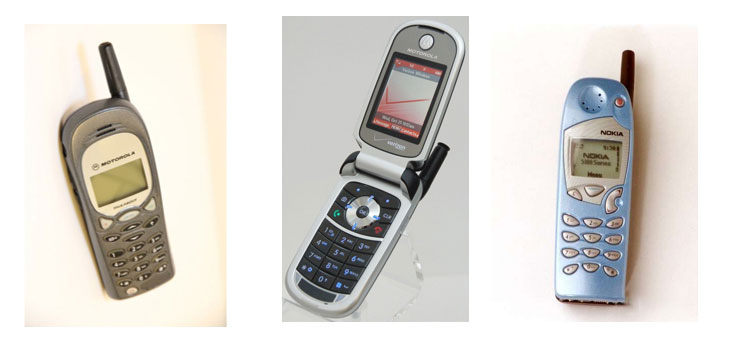
Photos of the “brick phones” from that era clearly show the long, thick metal rod atop the device: the earliest mobile phone antenna. Its technical name is Monopole Antenna, commonly known as a “whip antenna.”
1. Origin and Characteristics of Monopole Antennas
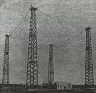
The monopole antenna is one of the oldest antenna forms. Marconi employed a monopole antenna structure in his transatlantic wireless communication experiments.
Marconi’s transmitter antenna featured a fan-shaped array of 50 copper wires slanted downward from a 48-meter-high horizontal support wire—considered the first practical monopole antenna. It was powered by a 70Hz spark generator. Later, four wooden towers were erected to form a square monopole antenna network, as shown in the illustration, with a transmission wavelength of 1000 meters.
As radio operating frequencies gradually increased, electromagnetic wave wavelengths shortened, leading to corresponding reductions in monopole antenna dimensions. For an extended period, it remained the most common antenna form in wireless equipment.
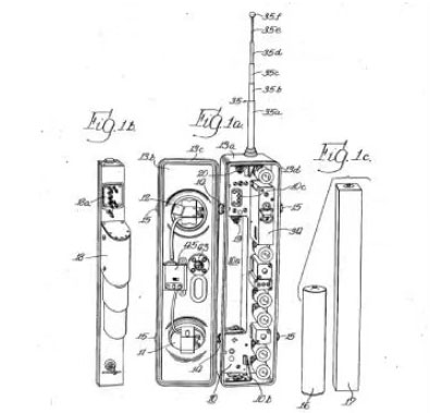
In 1944, Motorola explicitly adopted the monopole antenna structure in its first patent for mobile communication devices (US2439411A)—a design remarkably similar to later “brick phones.”
2. Why was the monopole antenna suitable for early mobile phones?
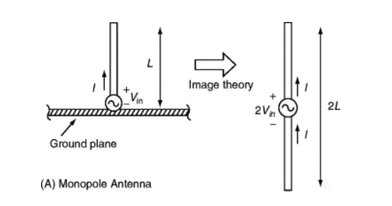
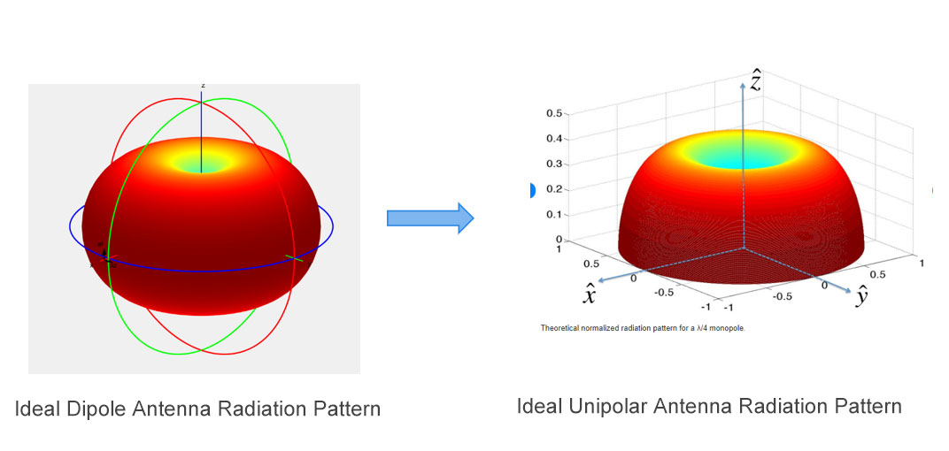
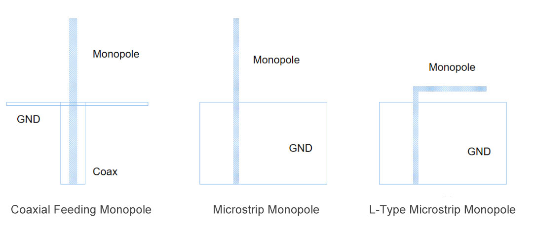
The monopole antenna features a simple structure and convenient tuning, with dimensions only half that of a dipole antenna operating at the same frequency. Its working principle is illustrated below: when vertically mounted on a ground plane that can be considered infinitely large, its single arm can be equivalent to the radiation of a dipole antenna’s two arms through the “mirror effect.”
When the monopole antenna has an effectively infinite ground plane, its radiation pattern can be considered half that of a dipole.
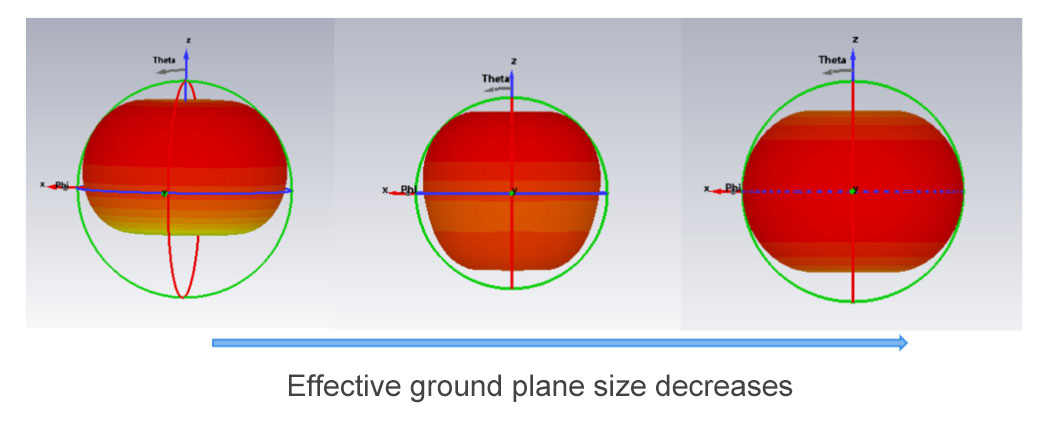
However, mobile devices cannot provide an infinitely large ground plane, so the actual radiation pattern of a monopole antenna varies. As the ground plane size gradually decreases, the monopole antenna’s directional characteristics increasingly resemble those of a dipole.
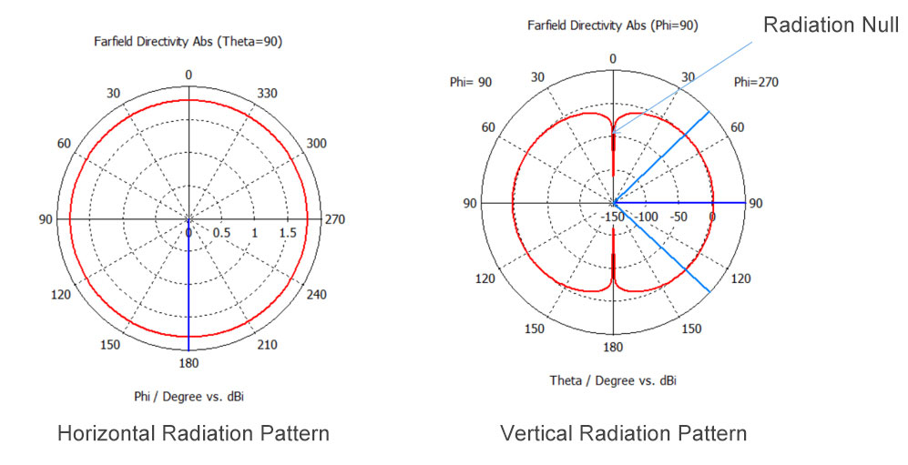
Additionally, monopole antennas exhibit a pronounced radiation dip along the vertical axis. This explains why Wi-Fi antennas may perform poorly when directly facing the device.
3. Miniaturization Attempts: Helical Monopoles
Due to the aesthetic drawbacks of long rods, engineers quickly explored miniaturization techniques:
Transforming straight radiation arms into helical structures
Or adopting retractable designs
This helical monopole antenna was widely used in early Motorola and Nokia phones, famously known as the “little radish head” antenna.
Yet the problem persisted: monopole antennas remained external components.
Thus a new question emerged: Could the monopole antenna be “folded” and placed directly inside the phone?
The Invisible Phone Antenna
Add Your Heading Text Here
Today’s smartphones rank among the most highly integrated consumer electronics with the most complex wireless environments in human history. A single phone often needs to support multiple wireless systems simultaneously—including cellular communications, Wi-Fi, Bluetooth, GNSS, and NFC. With cellular communication alone spanning over 60 frequency bands across 2G, 3G, 4G, and 5G.
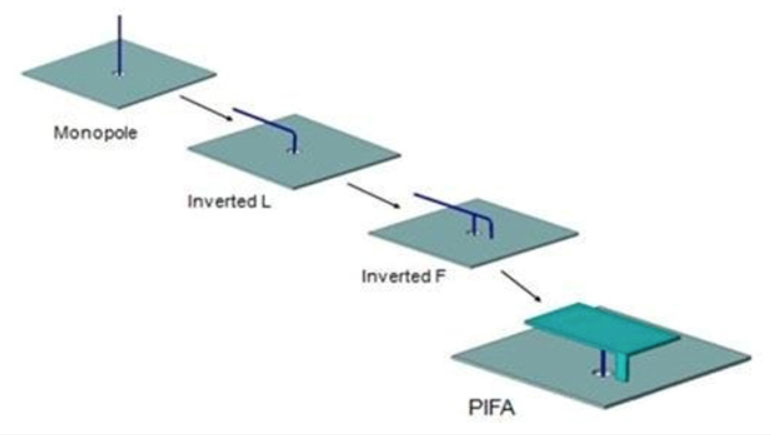
To further improve impedance matching for the inverted L, antenna engineers added a grounding point before the feed point, creating an inverted F antenna—the common IFA antenna. Extending the radiating arm into a planar structure to enhance bandwidth led to the planar inverted F antenna (PIFA). The diagram below illustrates the evolutionary path of the monopole antenna.
This evolution marked the transition of mobile phone antennas from “standalone components” to “integral structural elements” of the device.
2. PIFA: The Dawn of Built-in Antennas
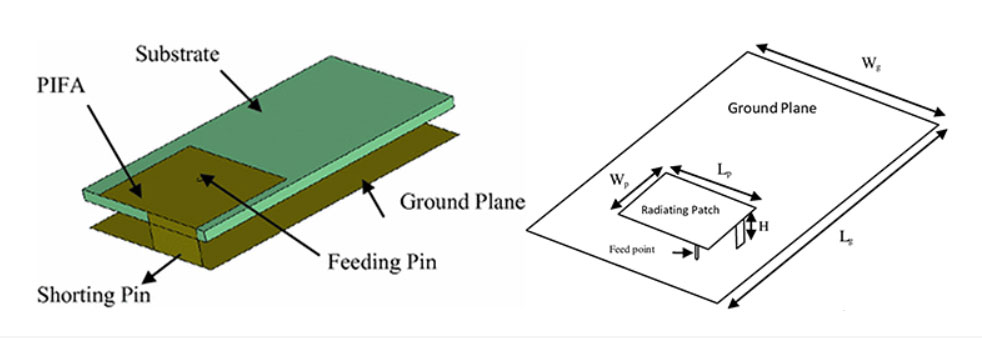
A typical PIFA structure comprises:
A planar radiating element
A ground plane (shorting hole)
A feed point
The underside serves as the phone’s ground plane.
This design required a certain thickness in the phone’s structure, but it represented the optimal solution for integrated antennas at the time and was widely adopted in Nokia handsets.
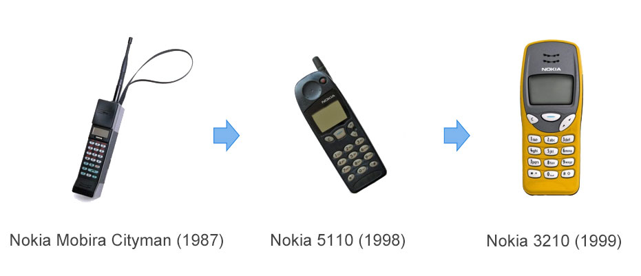
3. Nokia 3210: A Historic Turning Point
The Nokia 3210 was the first phone to utilize a PIFA antenna. In 1987, Nokia launched its inaugural mobile phone, the Nokia Mobira Cityman, which still employed a long, protruding antenna rod. In 1999, the Nokia 3210 became the first phone with a fully integrated antenna. It remains one of the best-selling models in mobile history, with cumulative sales exceeding 160 million units.
The Smartphone Era: Explosion in Antenna Quantity
As phones supported more wireless communication bands, the number of required antennas increased. The simplest approach was to physically mount each necessary antenna.
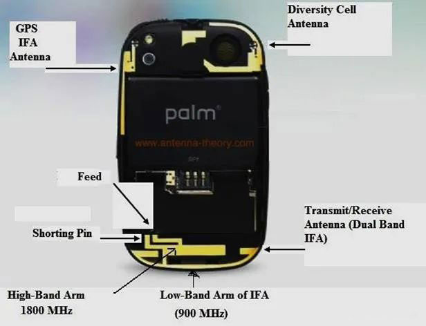
For example, the back of this Palm phone integrates a GPS antenna alongside GSM antennas for both the low-frequency 900MHz and high-frequency 1800MHz bands, with an additional auxiliary antenna positioned in the upper-right corner.
1. FPC Antennas: The Optimal Solution in the Plastic Era
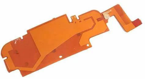
For a long time, mobile phone antennas were printed directly onto plastic back covers. This design offered excellent cost and space efficiency. These antennas, known as FPC antennas, were essentially external metal strips or other structural elements that extended beyond the printed circuit.
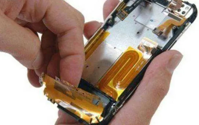
Apple used FPC antennas from the first-generation iPhone through the iPhone 3GS. They employed flexible antennas made by encapsulating copper foil within plastic film, which were then placed inside the phone’s plastic casing.
2. Frame Antenna: Structure as Antenna
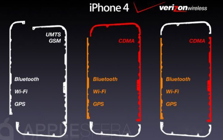
The 2010 launch of the iPhone 4 brought a truly revolutionary change to mobile antenna design. For the first time, the phone’s metal frame served as the radiator, seamlessly integrating antenna design with structural components. The antenna was no longer an “accessory,” but became an integral part of the device’s structure. Complex metal strips were soldered onto the sides of the casing to support multiple bands across different countries.
This novel antenna design also sparked numerous issues.
Many users reported that “when gripping the iPhone 4 tightly, its cellular signal would completely degrade to unusable levels within minutes.” The cause was clear: the frame antenna was directly exposed on the phone’s exterior, making it highly susceptible to external interference—especially when held in hand:
On one hand, the human body’s dielectric constant alters the antenna’s operating frequency, impairing its performance;
On the other hand, the method of setting different antenna frequencies through breaks in the metal band can easily fail if the human body, acting as a conductor, happens to touch these breaks.
In the later iPhone 4S, engineers solved the problem by adding more breaks to the metal band, achieving stable communication.
Conclusion
From the earliest whip antennas to today’s highly integrated frame and structural designs, mobile phone antenna evolution reflects decades of continuous innovation under extreme physical constraints. For this very reason, as we hold our sleek, lightweight smartphones today, we truly owe a huge round of applause to the communications engineers.For this very reason, as we hold our sleek, lightweight smartphones today, we truly owe a huge round of applause to the communications engineers.