Luneburg Lens Antenna & Reflector

Luneburg Lens Antenna & Reflector
A Luneburg Lens Antenna & Reflector is a dielectric-based microwave solution that enables high-gain performance, wide-angle coverage, and effective radar cross section (RCS) enhancement. This article outlines its working principles, structural design, key advantages, and typical applications across satellite tracking, radar systems, and navigation environments.
Table of contents
- Luneburg Technology
- Introduction
- Luneburg Lens Reflector Product Introduction
- Product Series
- Technical Performance Parameters
- Operating Conditions
1. Luneburg Technology
1.1 Technical Background
The Luneburg lens antenna was proposed by Rudolf Karl Lüneburg in 1944 and has a history spanning more than 80 years. Through continuous updates and improvements by engineers, this dielectric lens antenna technology is now widely used to manufacture low-cost, high-gain, and easy-to-deploy microwave antennas, primarily for applications such as satellite tracking by mobile receiving stations. Luneburg lens reflectors are used to enhance the effective radar cross-section of targets and are applied in radar target identification and for target drones/decoys.
1.2 Luneburg Lens
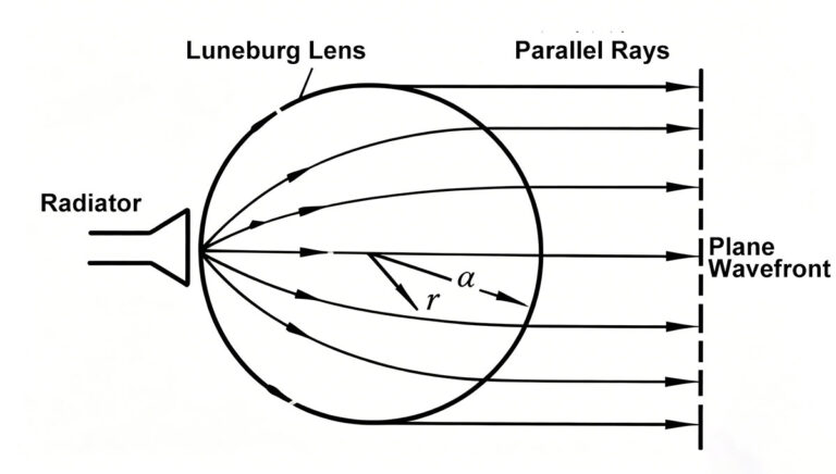
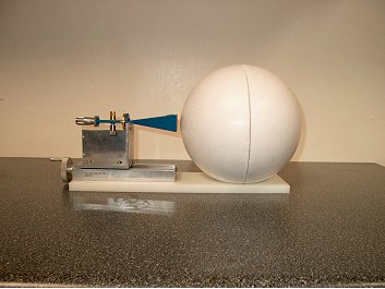
A Luneburg Lens is a layered dielectric sphere whose outer layer has a dielectric constant identical to or similar to that of air, with the dielectric constant increasing toward the center of the sphere. A Luneburg Lens constructed in this manner can focus incident electromagnetic waves. When a plane wave strikes the lens, it is focused by the lens onto the opposite end of the diameter perpendicular to the plane wavefront. Similarly, placing a feed source allows a plane wave to be formed and radiated from the spherical antenna aperture. With a Luneburg Lens antenna, simply moving the feed across the spherical surface enables a 360° beam scan.
1.3 Luneburg Lens Reflector
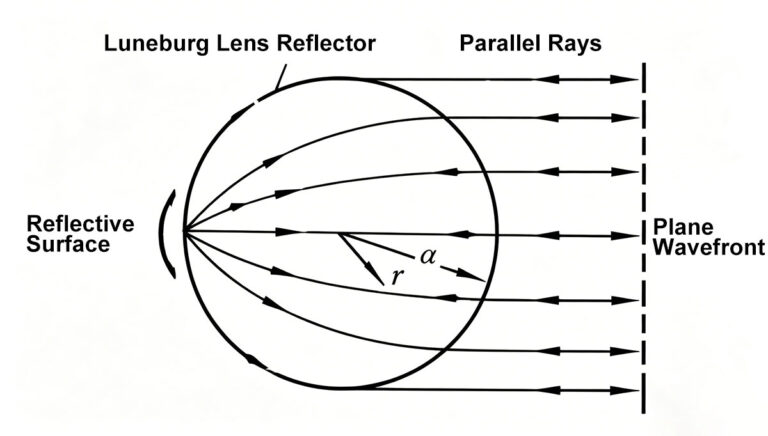
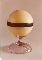
A Luneburg Lens reflector is constructed by coating half (or a portion) of the surface of a Luneburg Lens sphere with a metallic reflective layer. The resulting reflector can concentrate the intercepted electromagnetic waves and reflect them back with high gain, thereby providing a large radar cross-section. Its radar radar cross-section is proportional to the fourth power of its characteristic size and inversely proportional to the square of the wavelength.
1.4 Additional Information
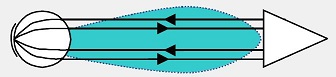
In certain situations, such as enhanced radar scanning of ships, monostatic Limbach reflectors—which transmit and receive from the same point—are required.
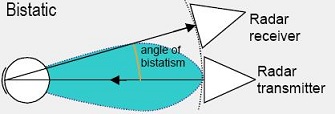
In applications such as target drones, where the radiation source and receiver are not at the same point, bistatic Limbach reflectors—which transmit and receive at a certain angle—are needed.
2. Introduction
Airplux Technology has over a decade of experience in Luneburg lens research, and its products are widely used by numerous organizations, including aerospace and marine agencies.
2.1 Technical Capabilities
Airplux Technology employs several leading experts in antenna technology and possesses extensive R&D experience in Luneburg lens antennas. The Luneburg lens product series undergoes rigorous laboratory and field testing during both the R&D and production phases.
2.2 Product Range
We offer two product series—Luneburg Lens Antennas and Luneburg Lens Reflectors—in various sizes and specifications, and can customize products to meet specific user requirements.
3. Luneburg Lens Reflector Product Introduction
3.1 Product Introduction
The Luneburg lens reflector is meticulously designed based on the principles of electromagnetic wave refraction and reflection.
It utilizes low-loss microwave dielectric materials, precisely controls the distribution of the refractive index within the sphere, and is manufactured using high-precision tooling and advanced forming processes. This represents a new type of passive echo enhancer.
3.1.1 Advantages
- Compact and lightweight, with extremely high reflection efficiency and a wide angular response. Its radar cross-section can be hundreds of times greater than that of a metal sphere of the same diameter.
- Cost-effective, with simple installation, adjustment, and maintenance. It features a long service life, requires no power supply, and offers excellent economic benefits.
- Since it emits no electromagnetic radiation, it poses no harm or interference to people or equipment. Additionally, it is not susceptible to electromagnetic interference, resulting in a very low failure rate and extremely high reliability. It is an energy-saving, environmentally friendly new product.
3.1.2 Scope of Application
- In the air: It can be mounted on aircraft, missiles, and targets to serve as a radar echo enhancer or a decoy for electronic countermeasures.
- On Land: It can be installed along waterways, in ports, and at airports as navigation and identification devices, or used as camouflage for artillery vehicles, tanks, military bases, and bridges.
- At Sea: Mounted on fishing vessels, naval ships, and lifeboats to increase the detection range and probability of radar detection, thereby preventing collisions and facilitating rescue and salvage operations. When installed around marine aquaculture zones, offshore exploration and construction areas, and military test zones, they serve as warning markers for approaching vessels.
Please carefully select the appropriate specifications—such as diameter and reflector shape and size—of the Luneburg Lens reflector based on the specific application.
3.1.3 Structural Features
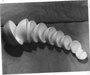
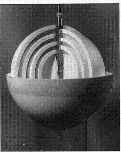
- The lens reflector is made of low-loss dielectric materials and is constructed by layering materials with varying dielectric constants.
- Each layer consists of two hemispheres. The outer shell is a fiberglass protective layer coated with colored paint, providing sealing, corrosion resistance, and weather resistance. The entire product forms a spherical structure.
3.1.4 Use and Maintenance
- The Luneburg Lens reflector should be installed in a location free from electromagnetic interference and with good visibility.
- During installation, align the red (or black, etc.) marker on the sphere toward the direction of maximum reflection; generally, visual alignment is sufficient. For omnidirectional reflection characteristics, position the M2 symmetrical plane of the lens reflector’s reflective surface horizontally, with a deviation not exceeding 3°.
- If the outer surface of the Luneburg lens reflector is dirty, it can be rinsed clean with water.
- Do not drill holes or embed other parts into the Luneburg lens reflector to avoid damage.
4. Product Series
Airplux Technology has over a decade of experience in Luneburg lens research, and its products are widely used by numerous organizations, including aerospace and marine agencies.
4.1 Product Categories
Luneburg Lens Reflector
Luneburg Lens Antenna
Microwave Antenna Design
Custom microwave antenna products with special performance requirements are designed according to customer needs.
Product Development and Testing
Field performance testing, anechoic chamber testing
4.2 Luneburg Lens Reflector Models
AP-1 Type: Monostatic (Single Transmitter/Receiver), conical solid angle (greater than 120 degrees)
AP-2 Type: Monostatic, 360-degree omnidirectional
AP-3 Type: Bistatic, 360-degree omnidirectional
AP-4 Type: Monostatic, hemispherical
Currently, these products are available in over ten different sizes and specifications. We can also design and customize special products with different dimensions and reflector coverage ranges according to customer requirements.
5. Technical Performance Parameters
AP-Type Luneburg Lens Reflector Technical Parameters Summary (Table 1):
|
Model |
Diameter (mm) |
Weight (g) |
Frequency Band |
Max. RCS (m²) |
Reflection Characteristics |
|
AP-06-I |
61 |
50 |
X |
0.18 |
Conical Angle > 120° |
|
AP-07-I |
76 |
85 |
X |
0.25 |
Conical Angle > 120° |
|
AP-09-I |
90 |
133 |
X |
0.5 |
Conical Angle > 120° |
|
AP-10-I |
103.6 |
200 |
X |
0.75 |
Conical Angle > 120° |
|
AP-12-I |
122 |
350 |
X |
1.46 |
Conical Angle > 120° |
|
AP-13-I |
132 |
436 |
X |
1.8 |
Conical Angle > 120° |
|
AP-14-I |
146 |
550 |
X |
2.3 |
Conical Angle > 120° |
|
AP-15-I |
156 |
680 |
X |
3 |
Conical Angle > 120° |
|
AP-16-I |
162 |
740 |
X |
3.3 |
Conical Angle > 120° |
|
AP-17-I |
178 |
972 |
X |
5 |
Conical Angle > 120° |
|
AP-190-I |
190.5 |
1260 |
X |
6.5 |
Conical Angle > 120° |
|
AP-19-I |
195 |
1300 |
X |
7 |
Conical Angle > 120° |
|
AP-20-I |
207 |
1600 |
X |
9 |
Conical Angle > 120° |
|
AP-22-I |
227 |
2100 |
X |
13 |
Conical Angle > 120° |
|
AP-25-I |
259 |
3100 |
X |
20 |
Conical Angle > 120° |
|
AP-27-I |
275 |
3420 |
X |
24 |
Conical Angle > 120° |
|
AP-30-I |
307 |
5200 |
X |
35 |
Conical Angle > 120° |
|
AP-39-I |
395 |
10600 |
X |
45 |
Conical Angle > 120° |
The AP-I-type Lumbard lens reflector is suitable for use across several octaves of wavelengths greater than 2 cm. Its radar cross-section is inversely proportional to the square of the wavelength, while the reflection angle remains constant.
The radar cross-section values shown in Table 1 correspond to a frequency of 9375 MHz; data for other frequency bands can be found in Table 2.
Table 2: Maximum RCS (square meters) for the AP-I-type Lumbard lens reflector
|
3G |
5G |
8G |
9G |
10G |
12.5G |
15G |
18G |
|
|
AP-06-1 |
0.02 |
0.04 |
0.12 |
0.16 |
0.18 |
0.27 |
0.32 |
0.37 |
|
AP-07-I |
0.03 |
0.06 |
0.16 |
0.23 |
0.25 |
0.35 |
0.43 |
0.5 |
|
AP-09-I |
0.05 |
0.12 |
0.33 |
0.46 |
0.5 |
0.7 |
0.85 |
1 |
|
AP-10-I |
0.08 |
0.18 |
0.5 |
0.7 |
0.75 |
1.1 |
1.3 |
1.5 |
|
AP-12-I |
0.16 |
0.35 |
0.97 |
1.3 |
1.46 |
2.14 |
2.53 |
2.92 |
|
AP-13-I |
0.18 |
0.48 |
1.2 |
1.68 |
1.8 |
2.41 |
3.01 |
3.61 |
|
AP-14-I |
0.23 |
0.61 |
1.53 |
2.1 |
2.29 |
3.06 |
3.82 |
4.59 |
|
AP-15-I |
0.3 |
0.8 |
2 |
2.8 |
3 |
4 |
5 |
6 |
|
AP-16-I |
0.35 |
0.93 |
2.33 |
3 |
3.3 |
4.66 |
5.5 |
7 |
|
AP-17-I |
0.5 |
1.2 |
3.3 |
5 |
5 |
6.5 |
8.5 |
10 |
|
AP-19-I |
0.8 |
1.8 |
5 |
6.4 |
7 |
9.1 |
11 |
14 |
|
AP-20-I |
1 |
2.2 |
6 |
8 |
9 |
12 |
15 |
18 |
|
AP-22-I |
1.3 |
3 |
8 |
11 |
13 |
15 |
18 |
20 |
|
AP-25-I |
2.3 |
5 |
13 |
17 |
20 |
24 |
27 |
27 |
|
AP-27-1 |
2.7 |
6 |
15 |
20 |
24 |
28 |
32 |
32 |
|
AP-30-I |
4.5 |
10 |
26 |
30 |
35 |
36 |
34 |
32 |
|
AP-39-I |
45 |
60 |
AP-2 Omnidirectional Model: 360-degree horizontal coverage, ±15-degree vertical coverage; RCS (Radar Cross Section) is 1/4 to 1/3 that of the AP-1 model of the same size and specifications.
6. Operating Conditions
AP-type Luneburg Lens reflectors are designed to operate normally under the following environmental conditions:
Operating temperature: -40°C to +55°C;
Relative humidity: Not exceeding 98%.