Electronic Product Antennas Guide: PCB, FPC and LDS Antennas
This Electronic Product Antennas Guide provides a concise overview of PCB, FPC, and LDS antennas used in modern electronic devices, covering their structures, advantages, limitations, and key design considerations to support practical antenna selection and integration.
Table of Contents
Introduction
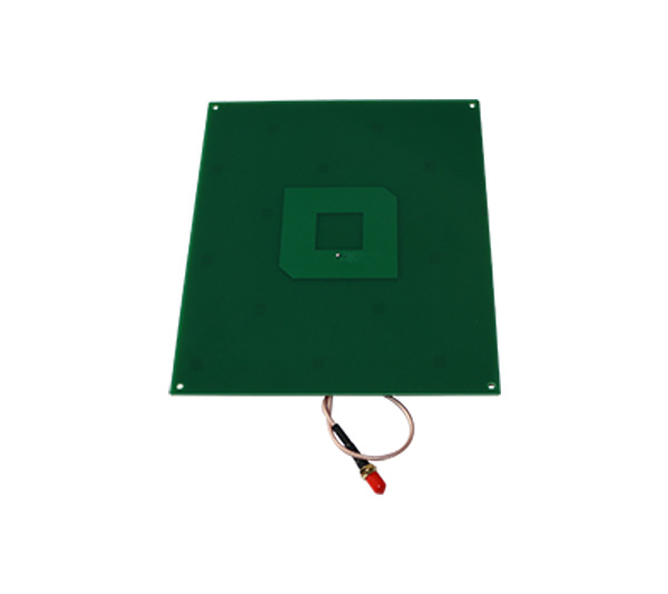
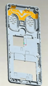
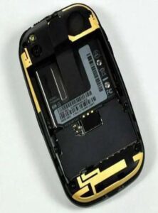
Types of Electronic Product Antennas
Design Considerations for Smart Devices
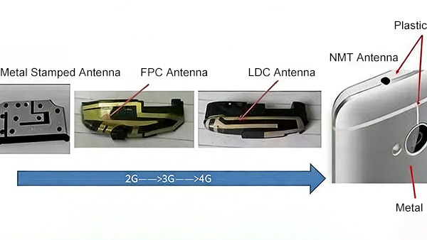
Evolution of Antenna Technologies
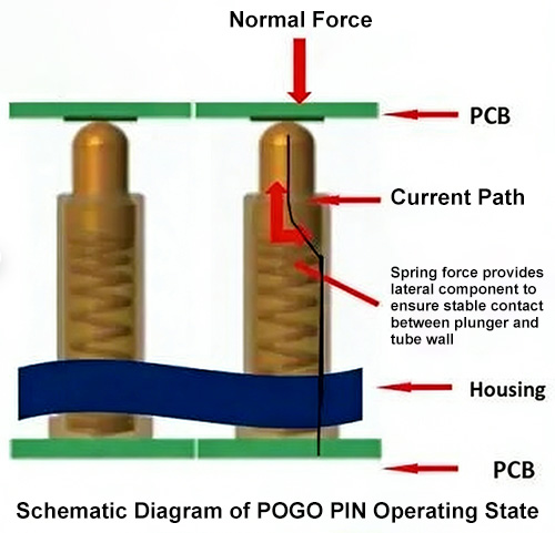
Common Antenna Design Considerations
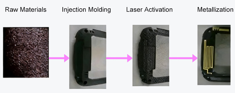
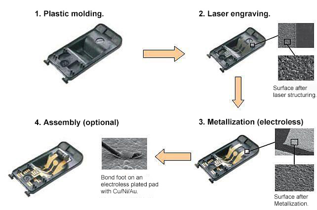
LDS Antenna Process Flow