Antenna Basics, Concepts & Theory

Antenna Basics, Concepts & Theory

This article introduces the Antenna Basics, Concepts & Theory, everything you need to know about the fundamentals of antenna theory and related basic knowledge.

The content will include below subjects:

1.Introduction to Antennas

2. Antenna Basics & Characteristics

-Antenna Gain
-Radiation Pattern
-Polarization
-VSWR

3.Types of Antennas

-Dipole Antenna
-Monopole Antenna
-Yagi-Uda Antenna
-Log-Periodic Antenna
-Microstrip (Patch) Antenna

1. Introduction to Antennas

What is an antenna and how does it work? 

In radio engineering, an antenna is the interface between radio waves propagating through space and electric currents moving in metal conductors, used with a transmitter or receiver. In transmission, a radio transmitter supplies an electric current to the antenna’s terminals, and the antenna radiates the energy from the current as electromagnetic waves (radio waves). In reception, an antenna intercepts some of the power of a radio wave in order to produce an electric current at its terminals, that is applied to a receiver to be amplified. Antennas are essential components of all radio equipment.

An antenna is an array of conductors (elements), electrically connected to the receiver or transmitter. Antennas can be designed to transmit and receive radio waves in all horizontal directions equally (omnidirectional antennas), or preferentially in a particular direction (directional, or high-gain, or “beam” antennas). An antenna may include components not connected to the transmitter, parabolic reflectors, horns, or parasitic elements, which serve to direct the radio waves into a beam or other desired radiation pattern.

Simply speaking:

An antenna is an electrical conductor or system of conductors.An antenna is a circuit element that provides a transition form a guided wave on a transmission line to a free space wave and it provides for the collection of electromagnetic energy.

Transmission – radiates electromagnetic energy into space.

Reception – collects electromagnetic energy from space.

In two-way communication, the same antenna can be used for transmission and reception.

2. Antenna Basics & Characteristics

Antenna Gain

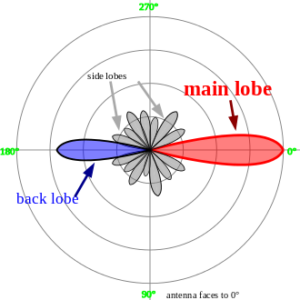
Gain is a parameter which measures the degree of directivity of the antenna’s radiation pattern. A high-gain antenna will radiate most of its power in a particular direction, while a low-gain antenna will radiate over a wide angle. The antenna gain, or power gain of an antenna is defined as the ratio of the intensity (power per unit surface area)  radiated by the antenna in the direction of its maximum output, at an arbitrary distance, divided by the intensity  radiated at the same distance by a hypothetical isotropic antenna which radiates equal power in all directions. This dimensionless ratio is usually expressed logarithmically in decibels, these units are called “decibels-isotropic” (dBi)

A second unit used to measure gain is the ratio of the power radiated by the antenna to the power radiated by a half-wave dipole antenna ; these units are called “decibels-dipole” (dBd)

Since the gain of a half-wave dipole is 2.15 dBi and the logarithm of a product is additive, the gain in dBi is just 2.15 decibels greater than the gain in dBd

Radiation Pattern

The radiation pattern of an antenna is a plot of the relative field strength of the radio waves emitted by the antenna at different angles in the far-field. It is typically represented by a three-dimensional graph, or polar plots of the horizontal and vertical cross sections. The pattern of an ideal isotropic antenna, which radiates equally in all directions, would look like a sphere. Many nondirectional antennas, such as monopoles and dipoles, emit equal power in all horizontal directions, with the power dropping off at higher and lower angles; this is called an omnidirectional pattern and when plotted looks like a torus or donut.

Radiation pattern - Antenna Basics, Concepts & Theory

Polarization

The polarization of an antenna refers to the orientation of the electric field (E-plane) of the radio wave with respect to the Earth’s surface and is determined by the physical structure of the antenna and by its orientation. A simple straight wire antenna will have one polarization when mounted vertically, and a different polarization when mounted horizontally. A vertical antenna will transmit a vertically polarized wave. The receive and transmit antennas need to possess the same polarization.

VSWR

VSWR (Voltage Standing Wave Ratio), is also referred to as Standing Wave Ratio (SWR). VSWR is a function of the reflection coefficient, which describes the power reflected from the antenna.The reflection coefficient is also known as s11 or return loss. The VSWR is always a real and positive number for antennas. The smaller the VSWR is, the better the antenna is matched to the transmission line and the more power is delivered to the antenna. The minimum VSWR is 1.0. In this case, no power is reflected from the antenna, which is ideal.

3. Types of Antennas

There are many different types of antenna in radio systems, antennas can be classified in carious and they are used with specialized properties for particular applications.

Dipole Antenna
A dipole antenna is the simplest type of radio antenna, consisting of a conductive wire rod that is half the length of the maximum wavelength the antenna is to generate. This wire rod is split in the middle, and the two sections are separated by an insulator. Each rod is connected to a coaxial cable at the end closest to the middle of the antenna.Dipole means “two poles.”

Monopole Antenna
A monopole antenna is half of a dipole antenna on top of a conducting ground plane. The most common type is a quarter-wave monopole where the antenna is approximately 1/4 of wavelength of radio waves. The radiation pattern is limited to above the ground plane of the antenna. These antennas find uses in mobile communications and internet networks.

Yagi-Uda Antenna
A Yagi–Uda antenna, commonly known as a Yagi antenna, is a directional antenna consisting of multiple parallel elements in a line, usually half-wave dipoles made of metal rods. Yagi–Uda antennas consist of a single driven element connected to the transmitter or receiver with a transmission line, and additional “parasitic elements” which are not connected to the transmitter or receiver: a so-called reflector and one or more directors.It was invented in 1926 by Shintaro Uda of Tohoku Imperial University, Japan,and (with a lesser role played by his colleague) Hidetsugu Yagi.

Log-Periodic Antenna
A log-periodic antenna (LP), also known as a log-periodic array or log-periodic aerial, is a multi-element, directional antenna designed to operate over a wide band of frequencies. It was invented by John Dunlavy in 1952.

The most common form of log-periodic antenna is the log-periodic dipole array or LPDA, The LPDA consists of a number of half-wave dipole driven elements of gradually increasing length, each consisting of a pair of metal rods. The dipoles are mounted close together in a line, connected in parallel to the feedline with alternating phase. Electrically, it simulates a series of two or three-element Yagi antennas connected together, each set tuned to a different frequency.

LPDA antennas look somewhat similar to Yagi antennas, in that they both consist of dipole rod elements mounted in a line along a support boom, but they work in very different ways. Adding elements to a Yagi increases its directionality, or gain, while adding elements to a LPDA increases its frequency response, or bandwidth.

Microstrip (Patch) Antenna
A microstrip antenna (also known as a printed antenna) usually means an antenna fabricated using microstrip techniques on a printed circuit board (PCB).It is a kind of internal antenna. They are mostly used at microwave frequencies. An individual microstrip antenna consists of a patch of metal foil of various shapes (a patch antenna) on the surface of a PCB (printed circuit board), with a metal foil ground plane on the other side of the board. Most microstrip antennas consist of multiple patches in a two-dimensional array. The antenna is usually connected to the transmitter or receiver through foil microstrip transmission lines. The radio frequency current is applied (or in receiving antennas the received signal is produced) between the antenna and ground plane. Microstrip antennas have become very popular in recent decades due to their thin planar profile which can be incorporated into the surfaces of consumer products, aircraft and missiles; their ease of fabrication using printed circuit techniques; the ease of integrating the antenna on the same board with the rest of the circuit, and the possibility of adding active devices such as microwave integrated circuits to the antenna itself to make active antennas.

The most common type of microstrip antenna is the patch antenna. Antennas using patches as constitutive elements in an array are also possible. A patch antenna is a narrowband, wide-beam antenna fabricated by etching the antenna element pattern in metal trace bonded to an insulating dielectric substrate, such as a printed circuit board, with a continuous metal layer bonded to the opposite side of the substrate which forms a ground plane. Common microstrip antenna shapes are square, rectangular, circular and elliptical, but any continuous shape is possible. Some patch antennas do not use a dielectric substrate and instead are made of a metal patch mounted above a ground plane using dielectric spacers; the resulting structure is less rugged but has a wider bandwidth. Because such antennas have a very low profile, are mechanically rugged and can be shaped to conform to the curving skin of a vehicle, they are often mounted on the exterior of aircraft and spacecraft, or are incorporated into mobile radio communications devices.

For more Antenna Basics, Concepts & Theory, please check here.

Close Menu